SLIDE DOOR ADJUSTMENT
CAUTION / NOTICE / HINT
The necessary procedures (adjustment, calibration, initialization or registration) that must be performed after parts are removed, installed or replaced during the slide door adjustment are shown below.
| Replacement Part or Procedure | Necessary Procedures | Effects / Inoperative when not Performed | Link |
|---|---|---|---|
| Disconnect cable from negative (-) battery terminal | Drive the vehicle until stop and start control is permitted (approximately 15 to 60 minutes) | Stop and Start System (for 2AR-FE) | |
| Stop and Start System (for 2GR-FKS) | |||
| Memorize steering angle neutral point | Panoramic View Monitor System | ||
| Initialize back door lock | Power Door Lock Control System | ||
| Initialize servo motor | Air Conditioning System | ||
| Reset slide door close position | Power Slide Door System | ||
| Reset back door close position | Power Back Door System |
CAUTION:
Some of these service operations affect the SRS airbag system. Read the precautionary notices concerning the SRS airbag system before servicing.
Tech Tips
-
Use the same procedure for the RH and LH sides.
-
The procedure listed below is for the LH side.
-
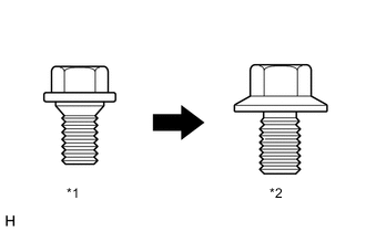
*1 Centering Bolt *2 Standard Bolt Centering bolts are used to mount the door hinge to the vehicle body and door. The door cannot be adjusted with the centering bolts on. Substitute the centering bolts for standard bolts when making adjustments.
-
A bolt without a torque specification is shown in the standard bolt chart.
PROCEDURE
-
PRECAUTION
Note
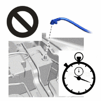
After turning the engine switch off, waiting time may be required before disconnecting the cable from the battery terminal. Therefore, make sure to read the disconnecting the cable from the battery terminal notice before proceeding with work.
-
DISCONNECT CABLE FROM NEGATIVE BATTERY TERMINAL
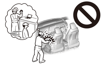
CAUTION:
-
Wait at least 90 seconds after disconnecting the cable from the negative (-) battery terminal to disable the SRS system.
-
If the airbag deploys for any reason, it may cause a serious accident.
Note
When disconnecting the cable, some systems need to be initialized after the cable is reconnected.
-
-
INSPECT SLIDE DOOR SUB-ASSEMBLY LH
-
Check that the clearance measurements of areas A to N are within the standard ranges.
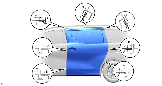
Standard Clearance A 3.2 to 6.2 mm (0.126 to 0.244 in.) B -1.5 to 1.5 mm (-0.059 to 0.059 in.) C 3.2 to 6.2 mm (0.126 to 0.244 in.) D -1.5 to 1.5 mm (-0.059 to 0.059 in.) E 4.1 to 7.1 mm (0.161 to 0.280 in.) F -1.7 to 1.3 mm (-0.067 to 0.051 in.) G 4.1 to 7.1 mm (0.161 to 0.280 in.) H -2.6 to 0.4 mm (-0.102 to 0.016 in.) I 4.0 to 7.0 mm (0.157 to 0.276 in.) J -2.8 to 0.2 mm (-0.110 to 0.008 in.) K 3.2 to 6.2 mm (0.126 to 0.244 in.) L -1.4 to 1.6 mm (-0.055 to 0.063 in.) M 3.2 to 6.2 mm (0.126 to 0.244 in.) N -1.1 to 1.9 mm (-0.043 to 0.075 in.)
-
-
DISCONNECT SLIDE DOOR NO. 3 WEATHERSTRIP LH
-
REMOVE REAR DOOR TRIM BOARD SUB-ASSEMBLY LH
-
ADJUST SLIDE DOOR SUB-ASSEMBLY LH
-
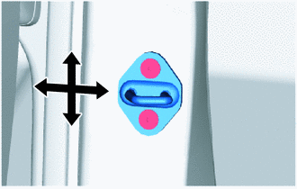
To adjust the door position vertically or horizontally at the slide door front lock striker plate assembly,loosen the bolts for the slide door down female stopper, loosen the striker screws using a T40 "TORX"socket wrench so that the striker can move, and then using a brass bar and hammer, adjust the strikerposition by tapping it lightly.
- Torque:
- 23 N*m { 235 kgf*cm, 17 ft.*lbf }
-
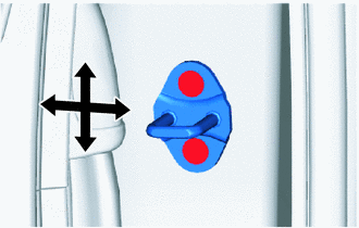
To adjust the door position vertically or horizontally at the slide door lock striker plate assembly, loosenthe striker screws using a T40 "TORX" socket wrench, and then using a brass bar and hammer, adjust theposition by tapping it lightly.
- Torque:
- 23 N*m { 235 kgf*cm, 17 ft.*lbf }
-
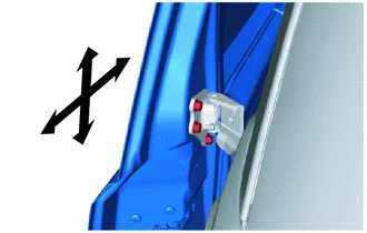
To adjust the door position in the vertical or front-to back directions at the rear edge of the door, loosen the bolts of the center slide door hinge assembly LH before making an adjustment.
- Torque:
- 19.5 N*m { 199 kgf*cm, 14 ft.*lbf }
-
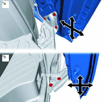
*a Door Side *b Vehicle Body Side To adjust the lower door seating position on the vehicle body surface vertically or to adjust the door position in the vertical and front-to-back directions, fully close the slide door, loosen the bolt of the lower slide door roller arm LH, and then check and adjust the door position.
- Torque:
- Door Side
- 19.5 N*m { 199 kgf*cm, 14 ft.*lbf }
- Vehicle Body Side
- 19 N*m { 194 kgf*cm, 14 ft.*lbf }
Tech Tips
To adjust the slide door lower roller base on the vehicle body side, disengage the slide door full open stop lock assembly and temporarily install the bolts.
-
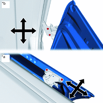
*a Door Side *b Vehicle Body Side To adjust the door position in the vertical, horizontal or front-to-back direction, loosen the bolts of the upper slide door roller assembly LH before making an adjustment.
- Torque:
- Door Side
- 11.5 N*m { 117 kgf*cm, 8 ft.*lbf }
- Vehicle Body Side
- 30 N*m { 306 kgf*cm, 22 ft.*lbf }
-
Temporarily tighten theslide door down female stopper, fully close the slide door to settle the stopper,and then fully tighten the stopper.
- Torque:
- 7.5 N*m { 76 kgf*cm, 66 in.*lbf }
-
After adjusting the door position, check the operation of the electricdoor lock system, slide door closer system, and power slide door system.
Tech Tips
If something contacts the power slide door touch sensor during an automaticclosing operation, the door will reverse.
-
-
INSTALL REAR DOOR TRIM BOARD SUB-ASSEMBLY LH
-
CONNECT SLIDE DOOR NO. 3 WEATHERSTRIP LH
-
CONNECT CABLE TO NEGATIVE BATTERY TERMINAL
Note
When disconnecting the cable, some systems need to be initialized after the cable is reconnected.
-
CHECK SRS WARNING LIGHT
-
PERFORM DIAGNOSTIC SYSTEM CHECK