SLIDE DOOR DISASSEMBLY
CAUTION / NOTICE / HINT
The necessary procedures (adjustment, calibration, initialization or registration) that must be performed after parts are removed, installed or replaced during the slide door disassembly/reassembly are shown below.
| Replacement Part or Procedure | Necessary Procedures | Effects / Inoperative when not Performed | Link |
|---|---|---|---|
| Disconnect cable from negative (-) battery terminal | Drive the vehicle until stop and start control is permitted (approximately 15 to 40 minutes) | Stop and start system | |
| Memorize steering angle neutral point | Panoramic view monitor system | ||
| Initialize back door lock | Power door lock control system | ||
| Initialize servo motor | Air conditioning system | ||
| Reset slide door close position | Power slide door system | ||
| Reset back door close position | Power back door system | ||
|
Initialize Power Window Control System |
|
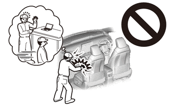
CAUTION:
Some of these service operations affect the SRS airbag system. Read the precautionary notices concerning the SRS airbag system before servicing.
Tech Tips
-
Use the same procedure for the RH and LH sides.
-
The procedure listed below is for the LH side.
-
Use the same procedure for RHD and LHD vehicles.
-
The procedures listed below are for LHD vehicles.
-
When removing the rear door glass sub-assembly LH, move the rear door glass sub-assembly LH to the lowest position before disconnecting the negative (-) battery terminal.
PROCEDURE
-
PRECAUTION
Note
After turning the engine switch off, waiting time may be required before disconnecting the cable from the negative (-) battery terminal. Therefore, make sure to read the disconnecting the cable from the negative (-) battery terminal notice before proceeding with work.
-
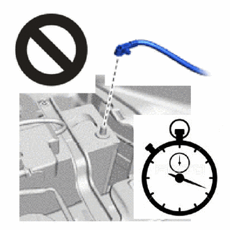
DISCONNECT CABLE FROM NEGATIVE BATTERY TERMINAL
CAUTION:
-
Wait at least 90 seconds after disconnecting the cable from the negative (-) battery terminal to disable the SRS system.
-
If the airbag deploys for any reason, it may cause a serious accident.
Note
When disconnecting the cable, some systems need to be initialized after the cable is reconnected.
-
-
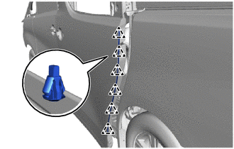
REMOVE NO. 3 SLIDE DOOR WEATHERSTRIP LH
-
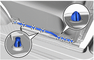
Using a clip remover, detach the clip and remove the No. 3 slide door weatherstrip LH.
-
-
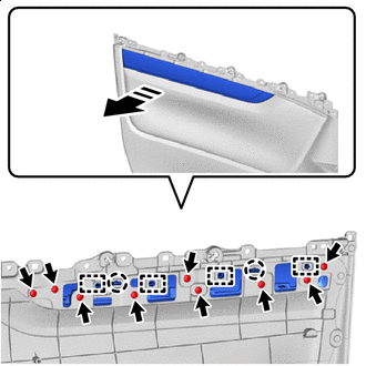
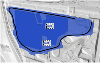
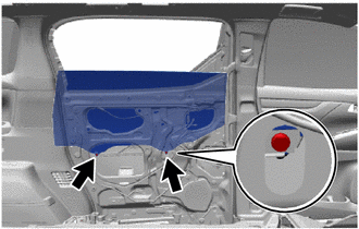
REMOVE REAR DOOR TRIM BOARD SUB-ASSEMBLY LH
-


Place Hands Here 
Order of Removal (1) 
Order of Removal (2) Detach the clip and claw as shown in the illustration.
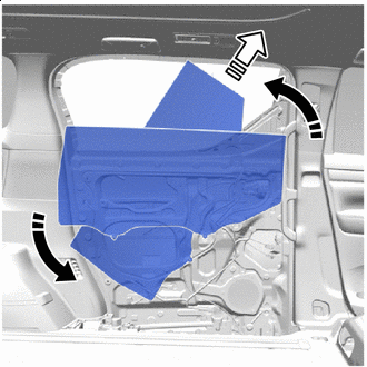
-
Disconnect each connector and remove the rear door trim board sub-assembly LH.
-
-
REMOVE REAR POWER WINDOW REGULATOR SWITCH ASSEMBLY
-
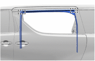
REMOVE REAR DOOR NO. 2 GLASS RUN LH
-
Remove the rear door No. 2 glass run LH from the rear door trim board sub-assembly LH.
-
-
REMOVE REAR NO. 2 SPEAKER ASSEMBLY
-
REMOVE REAR DOOR WIRING SUB-ASSEMBLY LH
-
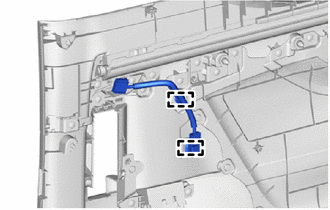
Detach the clamp and remove the rear door wiring sub-assembly LH.
-
-
REMOVE UPPER SLIDE DOOR TRIM BOARD LH (w/ Sunshade)
-
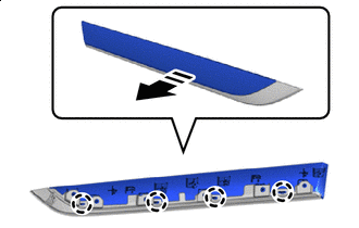
REMOVE REAR NO. 2 DOOR TRIM ORNAMENT BASE (w/ Sunshade)
-

Remove in this Direction Remove the 9 screws.
-
Detach the claw, guide and remove the rear No. 1 door trim ornament base together with the No. 3 side trim base plate as shown in the illustration.
-
-
REMOVE NO. 4 SIDE TRIM BASE PLATE (w/ Sunshade)
-
Remove in this Direction Detach the claw and remove the No. 4 side trim base plate from the rear No. 2 door trim ornament base. as shown in the illustration.
-
-
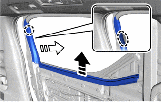
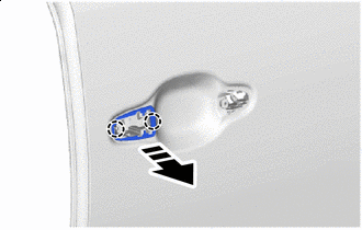
REMOVE SLIDE DOOR WINDOW GARNISH LH
-
Using a clip remover, detach the clip.
-
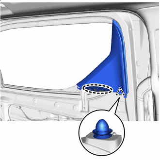
Place Hands Here Detach the clip as shown in the illustration.
-
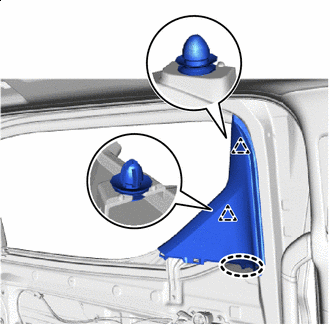
Place Hands Here Detach the clip and remove the slide door window garnish LH as shown in the illustration.
-
-
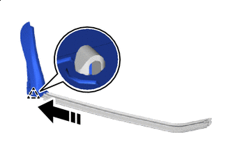
REMOVE REAR DOOR NO. 3 GLASS RUN LH
-
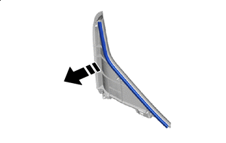
Remove in this Direction Remove the rear door No. 3 glass run LH from the slide door window garnish LH.
-
-
REMOVE REAR DOOR FRONT WINDOW GUIDE LH
-
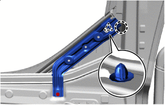
Insert Clip remover Here Remove the screw.
-
Using a clip remover, detach the clip and remove the rear door front window guide LH.
Note
When detaching the clip, be careful to remove the part without bending or damaging it.
-
-
REMOVE REAR DOOR INNER GLASS WEATHERSTRIP WITH GARNISH
-
Place Hands Here Remove in this Direction (1) 
Remove in this Direction (2) Detach the claw and remove the rear door inner glass weatherstrip with garnish as shown in the illustration.
-
-
REMOVE REAR DOOR REAR GUIDE BRACKET GARNISH LH
-
Remove in this Direction Detach the clip and remove the rear door rear guide bracket ganish LH from the rear door inner glass weatherstrip LH.
-
-
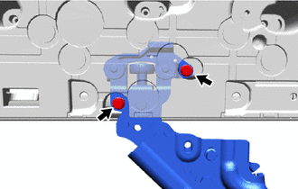
REMOVE SLIDE DOOR DOWN FEMALE STOPPER
-
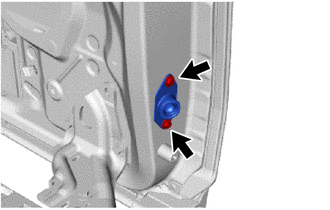
Remove the 2 bolts and slide door down female stopper.
-
-
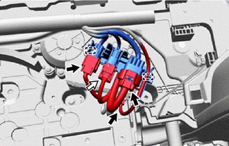
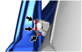
REMOVE SLIDE DOOR HANDLE ASSEMBLY LH
-
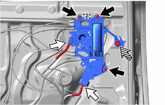
Bolt Connector 
Clip Disconnect the connector.
-
Remove the clip.
-
Remove the 3 bolts.
-
Detach the hook and disconnect the slide door handle assembly LH.
-
Disconnect Detach the snap as shown in the illustration.
-
Detach the guide and disconnect the each cable and remove the slide door handle assembly LH.
-
-
REMOVE REAR DOOR LOCKING CONTROL LINK SUB-ASSEMBLY LH
-
Remove in this Direction Detach the guide and remove the rear door locking control link sub-assembly LH from the slide door handle assembly LH as shown in the illustration.
-
-
REMOVE NO. 2 SIDE AIR BAG SENSOR ASSEMBLY
-
REMOVE SLIDE DOOR PANEL COVER SUB-ASSEMBLY LH
-
Remove in this Direction Remove the 2 screws.
-
Detach the claw, clamp and remove the slide door panel cover sub-assembly LH as shown in the illustration.
-
-
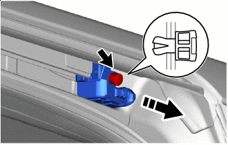
REMOVE WIRELESS DOOR LOCK BUZZER
-
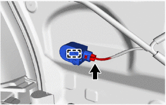
Disconnect the connector.
-
Detach the clamp and remove the wireless door lock buzzer.
-
-
REMOVE NO. 2 SLIDE DOOR SERVICE HOLE COVER
-

Butyl Tape Remove the 2 clamps.
-
Remove the No. 1 slide door service hole cover.
Note
Remove any remaining butyl tape from the slide door panel LH.
-
-
REMOVE REAR SPEAKER ASSEMBLY
-
REMOVE REAR DOOR GLASS SUB-ASSEMBLY LH
-
Remove the 2 bolts.
-
Remove in this Direction (1) Remove in this Direction (2) Remove the rear door glass sub-assembly LH as shown in the illustration.
Note
Do not damage the rear door glass sub-assembly LH.
-
-
REMOVE REAR DOOR GLASS RUN LH
-
Detach the guide and rear door glass run LH.
-
-
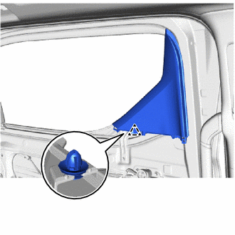
REMOVE SUNSHADE HOOK (w/ Sunshade)
-
Remove the 2 sunshade hooks.
-
-
REMOVE REAR DOOR WINDOW REGULATOR SUB-ASSEMBLY LH
-
Bolt Connector Temporarily Bolt Disconnect the connector.
-
Loosen the temporarily bolt.
Note
Do not remove the temporarily bolt. If the temporarily bolt is removed, the rear door window regulator sub-assembly LH may fall and become damaged.
-
Remove the 5 bolts and rear door window regulator sub-assembly LH.
-
Remove the temporarily bolt from the rear door window regulator sub-assembly LH.
-
-
REMOVE POWER WINDOW REGULATOR MOTOR ASSEMBLY LH
-
REMOVE REAR DOOR REAR WINDOW GUIDE SUB-ASSEMBLY LH
-
Bolt Nut Remove the nut and 2 bolts.
-
Remove in this Direction (1) Remove in this Direction (2) Remove the rear door rear window guide sub-assembly LH as shown in the illustration.
-
-
REMOVE REAR DOOR FRONT WINDOW FRAME MOULDING LH
-
REMOVE REAR DOOR UPPER WINDOW FRAME MOULDING LH
-
REMOVE REAR DOOR REAR WINDOW FRAME MOULDING LH
-
REMOVE REAR DOOR OUTSIDE MOULDING LH
-
REMOVE REAR DOOR BELT MOULDING LH
-
REMOVE CUSHION
-
Detach the claw and remove the 2 cushions.
-
-
REMOVE FRONT SLIDE DOOR LOCK ASSEMBLY LH
-
REMOVE REAR SLIDE DOOR LOCK ASSEMBLY LH
-
REMOVE REAR DOOR OUTSIDE HANDLE COVER LH
-
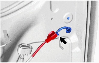
Disconnect the connector.
-
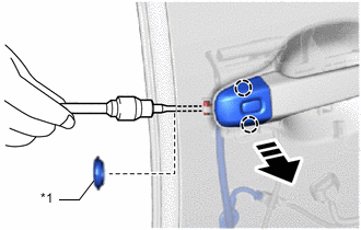
*1 Hole Plug Remove in this Direction Remove the hole plug.
-
Using a T30 "TORX" socket wrench, loosen the screw.
-
Detach the claw and remove the rear door outside handle cover LH as shown in the illustration.
-
-
REMOVE REAR DOOR OUTSIDE HANDLE ASSEMBLY LH
-
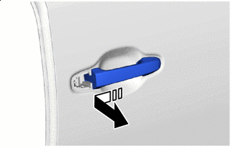
Remove in this Direction Remove the rear door outside handle assembly LH as shown in the illustration.
-
-
REMOVE REAR DOOR FRONT OUTSIDE HANDLE PAD
-
Remove in this Direction Detach the claw and remove the rear door front outside handle pad.
-
-
REMOVE REAR DOOR REAR OUTSIDE HANDLE PAD
-
Remove in this Direction Detach the claw and remove the rear door rear outside handle pad.
-
-
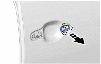
REMOVE REAR DOOR OUTSIDE HANDLE FRAME SUB-ASSEMBLY LH
-
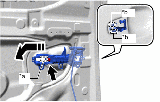
*a Grommet *b Guide Remove in this Direction Using a T30 "TORX" socket wrench, loosen the screw.
-
Detach the grommet, guide and remove the rear door outside handle frame sub-assebly LH as shown in the illustration.
-
-
REMOVE POWER SLIDE DOOR SENSOR ASSEMBLY LH
-
REMOVE REAR DOOR SCUFF PLATE LH
-
REMOVE REAR SIDE STEP SUPPORT LH
-
Remove the 2 bolts.
-
Using a clip remover, detach the clip and remove the rear side step support LH.
-
-
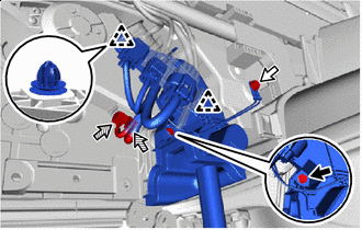
REMOVE REAR DOOR WIRE LH
-
Disconnect the airbag connector.
Note
When disconnecting any airbag connector, take care not to damage the airbag wire harness.
-
Push down the housing lock and slide the CPA. (At this time, the airbag connector cannot be disconnected yet.)
-
Push down the housing lock again and disconnect the airbag connector.
Note
Do not push down the upper part of the CPA shown in the illustration when disconnecting the airbag connector.
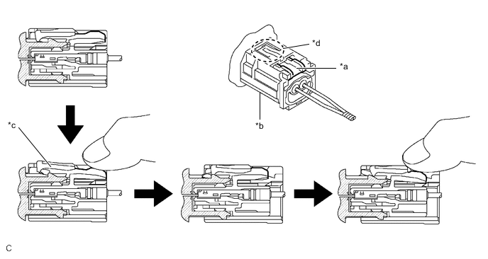
*a Housing Lock *b CPA *c Release the Connector Lock *d CPA Upper Part
-
-
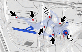
Airbag Connector Disconnect each connector.
-
Detach the clamp and disconnect the connetor holder.
-
Bolt Ground Bolt Connector Disconnect the 2 connectors.
-
Remove the bolt.
-
Remove the ground bolt and disconnect the ground wire.
-
Using a clip remover, detach the clip.
-
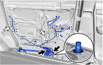
Bolt Ground Bolt Remove the 2 bolts.
-
Remove the 2 ground bolts and disconnect the 2 ground wires.
-
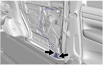
Detach the clamp, clip and remove the rear door wire LH.
-
-
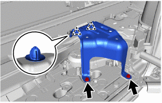
REMOVE SLIDE DOOR FULL OPEN STOP LOCK ASSEMBLY LH
-
Detach the clamp.
-
Remove the 2 bolts and slide door full open stop lock assembly LH.
-
-
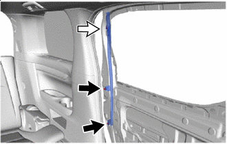
REMOVE REAR DOOR NO. 3 WEATHERSTRIP LH
-
Using a clip remover, detach the clip and remove the rear door No. 3 weatherstrip LH.
-
-
REMOVE SLIDE DOOR MUDGUARD LH
-
REMOVE NO. 1 SIDE MUDGUARD BRACKET LH
-
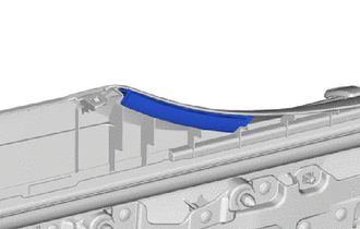
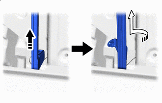
REMOVE UPPER SLIDE DOOR RAIL CUSHION LH
-
Remove in this Direction Remove the clip and upper slide door rail cushion LH as shown in the illustration.
-
-
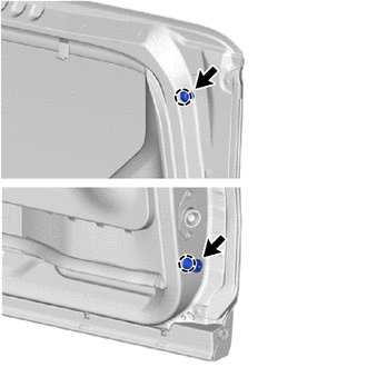
REMOVE LOWER SLIDE DOOR RAIL PLATE LH
-
Remove the clip and lower slide door rail plate LH.
-
-
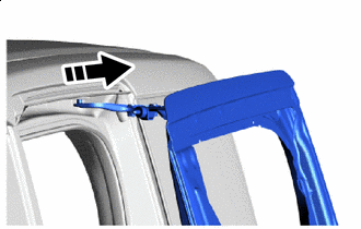
REMOVE SLIDE DOOR LH
-
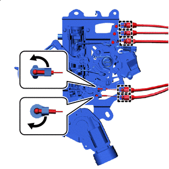
Move the slide door LH so that the 2 bolts are visible as shown in the illustration.
-
Remove the 2 bolts and disconnect the roller part of the lower slide door roller arm LH from the slide door motor unit LH.
-
Remove the 3 bolts and disconnect the center silde door hinge assembly LH.
Note
-
Support the lower portion of the slide door LH when disconnecting the center slide door hinge assembly LH, as the slide door LH becomes unstable.
-
Work with 2 or more persons when disconnecting the slide door LH in order to prevent deformation and damage.
-
-
Remove in this Direction Remove the slide door roller assembly LH as shown in the illustration.
-
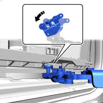
Counterclockwise Rotate the roller part of the lower slide door roller arm LH counterclockwise to disconnect the lower slide door roller arm LH from the cutout of the lower slide door motor unit LH.
-
-
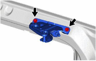
REMOVE CENTER SLIDE DOOR HINGE ASSEMBLY LH
-
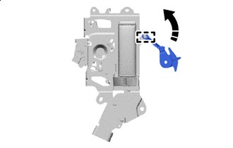
Move the center slide door hinge assembly LH to the front of the slide rail.
-
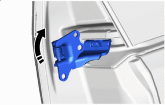
Remove in this Direction Remove the center slide door hinge assembly LH as shown in the illustration.
-
-
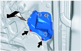
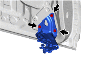
REMOVE SLIDE DOOR ROLLER ASSEMBLY LH
-
Remove the 2 bolts and slide door roller assembly LH.
-
-
REMOVE LOWER SLIDE DOOR ROLLER ARM LH
-
Remove the 3 bolts and lower slide door roller arm LH.
-