FRONT DOOR REASSEMBLY

CAUTION / NOTICE / HINT
Tech Tips
-
Use the same procedure for the RH and LH sides.
-
The procedure listed below is for the LH side.
-
Use the same procedure for RHD and LHD vehicles.
-
The procedures listed below are for LHD vehicles.
-
A bolt without a torque specification is shown in the standard bolt chart.
PROCEDURE
-
INSTALL FRONT DOOR MUDGUARD LH
-
INSTALL NO. 1 BLACK OUT TAPE LH
-
INSTALL NO. 2 BLACK OUT TAPE LH
-
INSTALL FRONT DOOR UPPER WINDOW FRAME MOULDING LH (w/ Upper Window Frame Moulding)
-
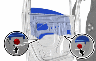
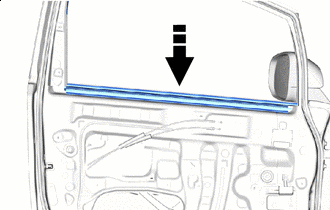
INSTALL FRONT DOOR OUTER GLASS WEATHERSTRIP LH
-
INSTALL FRONT DOOR NO. 2 WEATHERSTRIP LH
-
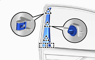
Attach the clip to install the front door No. 2 weatherstrip LH.
-
-
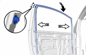
INSTALL FRONT DOOR WEATHERSTRIP LH
-
w/ Upper Window Frame Moulding:
Attach the clip to install the front door weatherstrip LH.
-
w/o Upper Window Frame Moulding:
Attach the clip to install the front door weatherstrip LH.
-
-
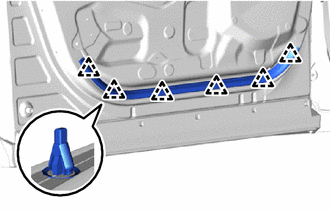
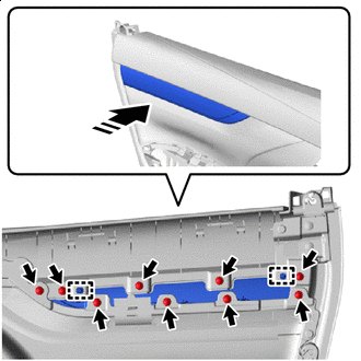
INSTALL FRONT DOOR PANEL CUSHION
-
Attach the claw to install 2 new front door panel cushions.
-
-
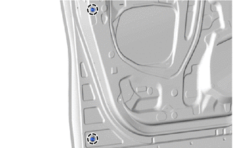
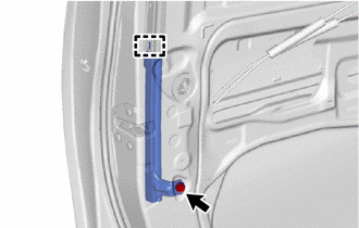
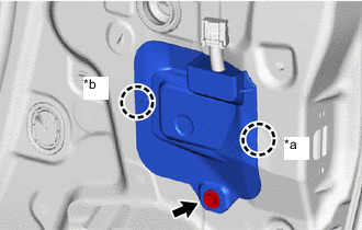
INSTALL FRONT DOOR CHECK ASSEMBLY LH
-
Apply MP grease to the sliding area of the front door check assembly LH.
-
When reusing a bolt:
-
Clean the threads of the bolt with non-residue solvent.
-
Apply adhesive to the threads of the bolt.
Adhesive Toyota Genuine Adhesive 1324, Three Bond 1324 or equivalent.
-
-
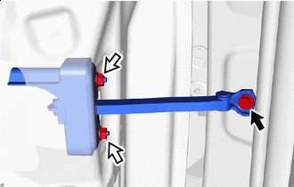

Bolt 
Nut Install the front door check assembly LH with the 2 nuts and bolt.
- Torque:
- Nut
- 8.0 N*m { 82 kgf*cm, 71 in.*lbf }
- Bolt
- 29 N*m { 296 kgf*cm, 21 ft.*lbf }
-
-
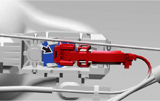
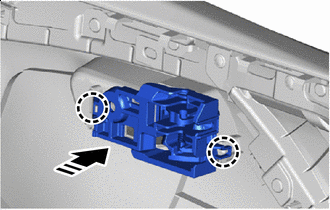
INSTALL FRONT DOOR LOCK OPEN ROD LH
-
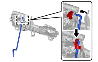

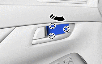
Install in this Direction Attach the snap to install the front door lock open rod LH to the front door outside handle frame sub-assembly LH as shown in the illustration.
-
-
INSTALL FRONT DOOR OUTSIDE HANDLE FRAME SUB-ASSEMBLY LH
-
Apply MP grease to the sliding area of the front door outside handle frame sub-assembly LH.
-
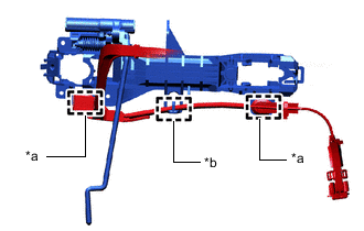
*a Clamp *b Guide Attach the guide and clamp to connect the wire harness.
-
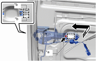
*a Grommet *b Guide Install in this Direction Attach the grommet and guide to install the front door outside handle frame sub-assembly LH as shown in the illsutration.
-
Using a T30 "TORX" socket wrench, install the screw.
- Torque:
- 7.0 N*m { 71 kgf*cm, 62 in.*lbf }
-
-
INSTALL FRONT DOOR INSIDE LOCKING CABLE ASSEMBLY LH
-
INSTALL FRONT DOOR LOCK REMOTE CONTROL CABLE ASSEMBLY LH
-
INSTALL FRONT DOOR LOCK COVER SUB-ASSEMBLY LH
-
INSTALL FRONT DOOR WITH MOTOR LOCK ASSEMBLY LH
-
INSTALL FRONT DOOR REAR OUTSIDE HANDLE PAD
-
Install in this Direction Attach the claw to install the front door rear outside handle pad.
-
-
INSTALL FRONT DOOR FRONT OUTSIDE HANDLE PAD
-
Install in this Direction Attach the claw to install the front door front outside handle pad.
-
-
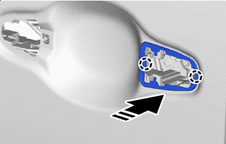
INSTALL FRONT DOOR OUTSIDE HANDLE ASSEMBLY LH
-
Install in this Direction Install the front door outside handle assembly LH as shown in the illustration.
-
Connect the connector.
-
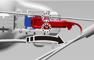
Install in this Direction Attach the claw to close the connector cover as shown in the illustration.
-
-
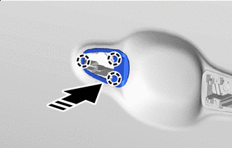
INSTALL FRONT DOOR OUTSIDE HANDLE COVER LH (for Driver Side)
-
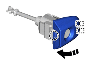
Install in this Direction Attach the guide and claw to install the front door outside handle cover LH as shown in the illustration.
-
-
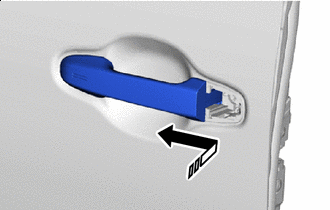
INSTALL FRONT DOOR OUTSIDE HANDLE COVER WITH LOCK CYLINDER ASSEMBLY (for Driver Side)
-
Apply MP grease to the sliding area of the front door outside handle cover with lock cylinder assembly.
-
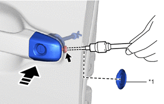
*1 Hole Plug Install in this Direction Install the front door outside handle cover with lock cylinder assembly as shown in the illustration.
Tech Tips
Check that the front door lock cylinder assembly is inserted into the front door lock with motor assembly LH.
-
Using a T30 "TORX" socket wrench, install the screw.
- Torque:
- 7.0 N*m { 71 kgf*cm, 62 in.*lbf }
-
Install the hole plug.
-
-
INSTALL FRONT DOOR OUTSIDE HANDLE COVER RH (for Front Passenger Side)
-
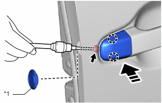
*1 Hole Plug Install in this Direction Attach the claw to install the front door outside handle cover LH as shown in the illustration.
-
Using a T30 "TORX" socket wrench, install the screw.
- Torque:
- 7.0 N*m { 71 kgf*cm, 62 in.*lbf }
-
Install the hole plug.
-
-
INSTALL FRONT DOOR REAR LOWER FRAME SUB-ASSEMBLY LH
-
Attach the guide to install the front door rear lower frame sub-assembly LH.
-
Install the bolt.
- Torque:
- 7.5 N*m { 76 kgf*cm, 66 in.*lbf }
-
-
INSTALL POWER WINDOW REGULATOR MOTOR ASSEMBLY LH
-
INSTALL FRONT DOOR WINDOW REGULATOR SUB-ASSEMBLY LH
-
Apply MP grease to the sliding area of the front door windoow regulator sub-assembly LH.
-
Temporarily install the temporarily bolt to the front door window regulator sub-assembly LH.
-
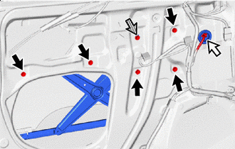
Bolt Connector 
Temporarily Bolt Install the front door window regulator sub-assembly LH with the temporarily bolt and 5 bolts.
- Torque:
- Temporarily Bolt
- 7.5 N*m { 76 kgf*cm, 66 in.*lbf }
- Bolt
- 7.5 N*m { 76 kgf*cm, 66 in.*lbf }
-
Connect the connector.
-
-
INSTALL FRONT DOOR GLASS SUB-ASSEMBLY LH
-
Connect the multiplex network master switch assembly.
-
Connect the cable to the negative (-) battery terminal.
-
Move the front door window regulator sub-assembly LH so that the front door glass sub-assembly LH bolts can be seen.
-
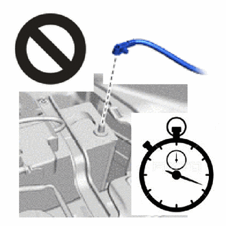
Disconnect the cable from the negative (-) battery terminal.
CAUTION:
-
Wait at least 90 seconds after disconnecting the cable from the negative (-) battery terminal to disable the SRS system.
-
If the airbag deploys for any reason, it may cause a serious accident.
Note
When disconnecting the cable, some systems need to be initialized after the cable is reconnected.
-
-
Disconnect the multiplex network master switch assembly.
-
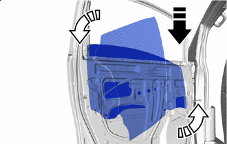
Install in this Direction (1) 
Install in this Direction (2) Temporarily install the front door glass sub-assembly LH as shown in the illustration.
Note
Be careful not to damage the front door glass sub-assembly LH.
-
Install the front door glass sub-assembly LH with the 2 bolts.
- Torque:
- 7.5 N*m { 76 kgf*cm, 66 in.*lbf }
-
Install the hole plug.
-
-
INSTALL FRONT DOOR GLASS RUN LH
-
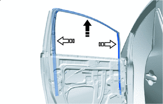
Install in this Direction (1) Install in this Direction (2) w/ Upper Window Frame Moulding:
Install the front door glass run LH as shown in the illustration.
-
Install in this Direction (1) Install in this Direction (2) w/o Upper Window Frame Moulding:
-
Install the front door glass run LH as shown in the illustration.
-
Attach the clip.
-
-
-
INSTALL FRONT DOOR FRONT WINDOW FRAME MOULDING LH
-
INSTALL FRONT DOOR REAR WINDOW FRAME MOULDING LH
-
INSTALL FRONT NO. 1 SPEAKER ASSEMBLY
-
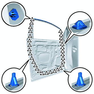
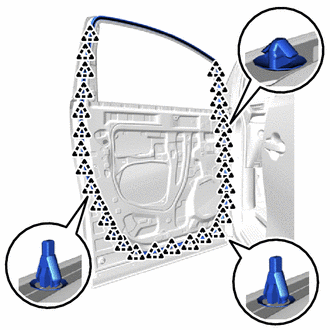
INSTALL FRONT DOOR SERVICE HOLE COVER LH
-
Apply new butyl tape to the front door panel.
-
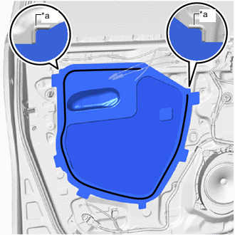
*a Reference Point 
Butyl Tape Pass the front door inside locking cable assembly LH and front door lock remote control cable assembly LH through a new front door service hole cover LH, and then attach the front door service hole cover LH using the reference points on the front door panel.
Tech Tips
-
Securely install the front door service hole cover LH to prevent wrinkles and air bubbles.
-
There should be no wrinkles or folds after installing the front door service hole cover LH.
-
After installing the front door service hole cover LH, check the seal quality.
-
-
-
INSTALL OUTER MIRROR CONTROL ECU ASSEMBLY (w/ Reverse Shift-linked Mirror)
-
INSTALL OUTER REAR VIEW MIRROR ASSEMBLY LH
-
INSTALL OUTER MIRROR PROTECTOR
-
*a Claw A *b Claw B Attach the claw B.
-
Attach the claw A to install a new outer mirror protector with the screw.
-
-
INSTALL OUTER MIRROR INSTALL HOLE COVER LH
-
INSTALL DOOR SIDE AIR BAG SENSOR LH
-
INSTALL FRONT DOOR INNER GLASS WEATHERSTRIP LH
-
Install in this Direction Install the front door inner glass weatherstip LH as shown in the illustration.
-
-
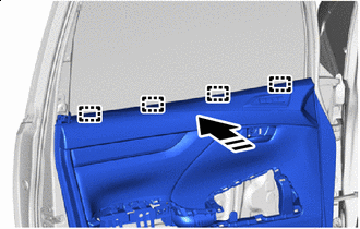
INSTALL FRONT DOOR SPEAKER GRILLE SUB-ASSEMBLY LH (w/ Seat Memory Switch)
-
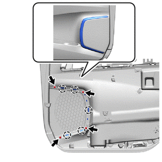
Attach the claw to temporarily install the front door speaker grille sub-assembly LH to the front door trim board sub-assembly LH.
-
Install the front door speaker grille sub-assembly LH to the front door trim board sub-assembly LH with the 4 spacers and 4 screws.
-
-
INSTALL NO. 2 SIDE TRIM BASE PLATE (w/ Seat Memory Switch)
-
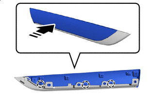
Install in this Direction Attach the claw to install the No. 2 side trim base plate to the front No. 2 door trim ornament base.
-
-
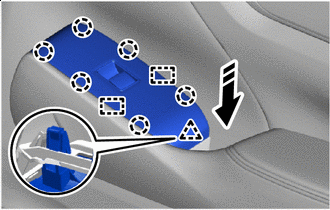
INSTALL FRONT NO. 2 DOOR TRIM ORNAMENT BASE (w/ Seat Memory Switch)
-
Install in this Direction Attach the guide.
-
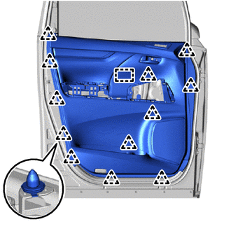
Install the front No. 2 door trim ornament base together with the No. 2 side trim base plate with the 9 screws as shown in the illustration.
-
-
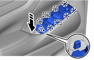
INSTALL FRONT DOOR TRIM ORNAMENT SUB-ASSEMBLY LH (w/o Seat Memory Switch)
-
Install in this Direction Attach the guide.
-
Install the front door trim ornament sub-assembly LH with the 9 screws as shown in the illustration.
-
-
INSTALL SEAT MEMORY SWITCH (w/ Seat Memory Switch)
-
INSTALL FRONT DOOR INSIDE HANDLE SUB-ASSEMBLY LH
-
Install in this Direction Attach the claw to install the front door inside handle sub-assembly LH to the front door trim board sub-assembly LH.
-
-
INSTALL FRONT DOOR TRIM BOARD SUB-ASSEMBLY LH
-
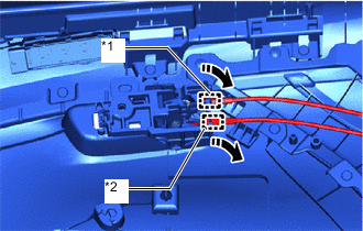
*1 Front Door Inside Locking Cable Assembly LH *2 Front Door Lock Remote Control Cable Assembly LH Install in this Direction Attach the clamp to connect the front door lock remote control cable assembly LH and front door inside locking cable assembly LH.
-
Connect each connector.
-
Install in this Direction Attach the guide as shown in the illustration.
-
Attach the boss and clip to install the front door trim board sub-assembly LH.
-
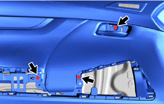
Install the 3 screws.
-
-
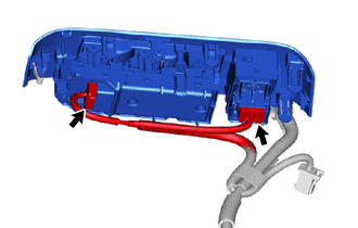
INSTALL COURTESY LIGHT ASSEMBLY (w/ Courtesy Light)
-
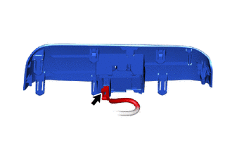
INSTALL REFLEX REFLECTOR (w/o Courtesy Light)
-
Connect the connector.
-
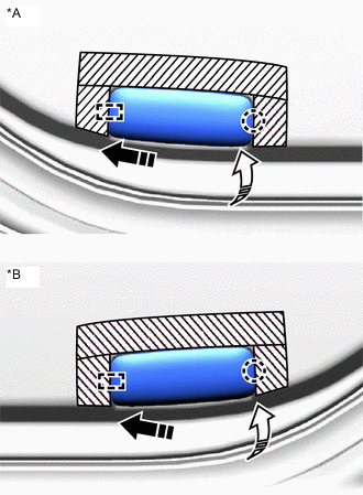
*A for LH Side *B for RH Side 
Protective Tape Install in this Direction (1) Install in this Direction (2) Attach the guide and claw to install the reflex reflector as shown in the illustration.
-
Remove the protective tape.
-
-
INSTALL FRONT ARMREST ASSEMBLY LH
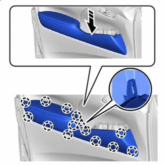
Install in this Direction
-
Attach the claw and clip to install the front armrest assembly LH.
-
-
INSTALL MULTIPLEX NETWORK MASTER SWITCH ASSEMBLY (for Driver Side)
-
INSTALL OUTER MIRROR SWITCH ASSEMBLY (for Driver Side)
-
INSTALL POWER WINDOW REGULATOR MASTER SWITCH ASSEMBLY WITH FRONT DOOR ARMREST BASE PANEL (for Driver Side)
-
Connect the 2 connectors.
-
Install in this Direction Attach the guide, claw and clip to install the power window regulator master switch assembly with front door armrest base panel as shown in the illustration.
-
-
INSTALL POWER WINDOW REGULATOR SWITCH ASSEMBLY (for Front Passenger Side)
-
INSTALL POWER WINDOW REGULATOR SWITCH ASSEMBLY WITH FRONT DOOR ARMREST BASE PANEL (for Front Passenger Side)
-
Connect the connector.
-
Install in this Direction Attach the guide, claw and clip to install the power window regulator switch assembly with front door armrest base panel as shown in the illustration.
-
-
INSTALL FRONT DOOR INSIDE HANDLE BEZEL PLUG LH
-
Install in this Direction Attach the claw to install the front door inside handle bezel plug LH as shown in the illustration.
-
-
INSTALL LOWER DOOR FRAME GARNISH LH
-
Attach the guide and clip to install the lower door frame garnish LH.
-
-
CONNECT CABLE TO NEGATIVE BATTERY TERMINAL
Note
When disconnecting the cable, some systems need to be initialized after the cable is reconnected.
-
CHECK SRS WARNING LIGHT
-
PERFORM DIAGNOSTIC SYSTEM CHECK
-
INITIALIZE POWER WINDOW CONTROL SYSTEM
-
CHECK POWER WINDOW CONTROL SYSTEM
-
CHECK POWER DOOR LOCK CONTROL SYSTEM