FRONT DOOR DISASSEMBLY

CAUTION / NOTICE / HINT
The necessary procedures (adjustment, calibration, initialization or registration) that must be performed after parts are removed, installed or replaced during the front door disassembly/reassembly are shown below.
| Replacement Part or Procedure | Necessary Procedures | Effects / Inoperative when not Performed | Link |
|---|---|---|---|
| Disconnect cable from negative (-) battery terminal | Drive the vehicle until stop and start control is permitted (approximately 15 to 40 minutes) | Stop and start system | |
| Memorize steering angle neutral point | Panoramic view monitor system | ||
| Initialize back door lock | Power door lock control system | ||
| Initialize servo motor | Air conditioning system | ||
| Reset slide door close position | Power slide door system | ||
| Reset back door close position | Power back door system | ||
|
Initialize Power Window Control System |
|
CAUTION:
Some of these service operations affect the SRS airbag system. Read the precautionary notices concerning the SRS airbag system before servicing.
Tech Tips
-
Use the same procedure for the RH and LH sides.
-
The procedure listed below is for the LH side.
-
Use the same procedure for RHD and LHD vehicles.
-
The procedures listed below are for LHD vehicles.
-
Fully open the front door glass sub-assembly LH before proceeding with work.
PROCEDURE
-
PRECAUTION
Note
After turning the engine switch off, waiting time may be required before disconnecting the cable from the negative (-) battery terminal. Therefore, make sure to read the disconnecting the cable from the negative (-) battery terminal notice before proceeding with work.
-
DISCONNECT CABLE FROM NEGATIVE BATTERY TERMINAL
CAUTION:
-
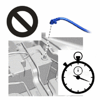
Wait at least 90 seconds after disconnecting the cable from the negative (-) battery terminal to disable the SRS system.
-
If the airbag deploys for any reason, it may cause a serious accident.
Note
When disconnecting the cable, some systems need to be initialized after the cable is reconnected.
-
-
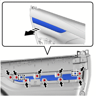
REMOVE LOWER DOOR FRAME GARNISH LH
-
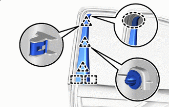

Place Hands Here Detach the clip as shown in the illustration.
-
Detach the guide and remove the lower door frame garnish LH.
-
-
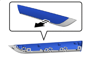
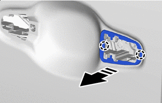
REMOVE FRONT DOOR INSIDE HANDLE BEZEL PLUG LH
-

Remove in this Direction Using moulding remover A, detach the claw and remove the front door inside handle bezel plug LH as shown in the illustration.
-
-
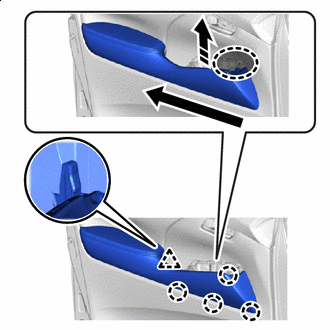
REMOVE POWER WINDOW REGULATOR MASTER SWITCH ASSEMBLY WITH FRONT DOOR ARMREST BASE PANEL (for Driver Side)
-
Using moulding remover D, detach the clip, claw and guide.
-
Disconnect the 2 connectors and remove the power window regulator master switch assembly with front door armrest base panel.
-
-
REMOVE OUTER MIRROR SWITCH ASSEMBLY (for Driver Side)
-
REMOVE MULTIPLEX NETWORK MASTER SWITCH ASSEMBLY (for Driver Side)
-
REMOVE POWER WINDOW REGULATOR SWITCH ASSEMBLY WITH FRONT DOOR ARMREST BASE PANEL (for Front Passenger Side)
-
Using moulding remover D, detach the clip, claw and guide.
-
Disconnect the connector and remove the power window regulator switch assembly with front door armrest base panel.
-
-
REMOVE POWER WINDOW REGULATOR SWITCH ASSEMBLY (for Front Passenger Side)
-
REMOVE FRONT ARMREST ASSEMBLY LH
-
Place Hands Here 
Order of Removal Remove in this Direction Detach the clip and claw as shown in the illustration.
-
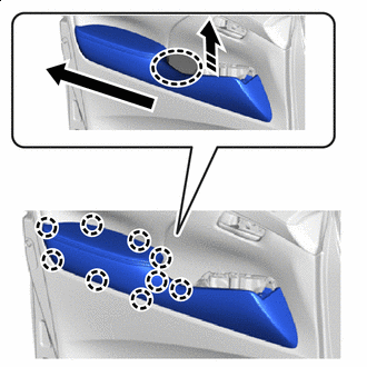
Place Hands Here Order of Removal Remove in this Direction Detach the clip and remove the front armrest assembly LH.
-
-
REMOVE COURTESY LIGHT ASSEMBLY (w/ Courtesy Light)
-
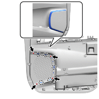
REMOVE REFLEX REFLECTOR (w/o Courtesy Light)
-
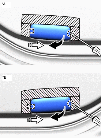
*A for LH side *B for RH side 
Protective Tape Remove in this Direction (1) 
Remove in this Direction (2) Put protective tape around the reflex reflector.
-
Using a thin-bladed screwdriver, detach the claw and guide.
Tech Tips
Tape the thin-bladed screwdriver tip before use.
-
Disconnect the connector and remove the reflex reflector.
-
-
REMOVE FRONT DOOR TRIM BOARD SUB-ASSEMBLY LH
-
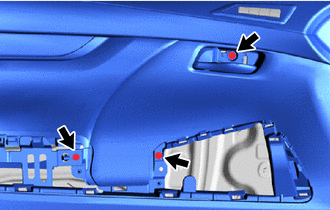
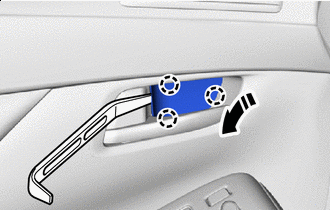
Remove the 3 screws.
-
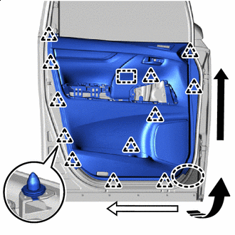
Place Hands Here Order of Removal (1) 
Order of Removal (2) Remove in this Direction Detach the clip and boss as shown in the illustration.
-
Disconnect each connector.
-
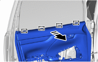
Remove in this Direction Detach the guide and remove the front door trim board sub-assembly LH as shown in the illustration.
-
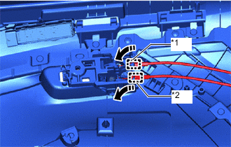
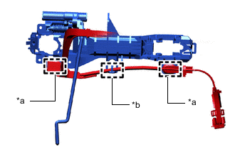
*1 Front Door Inside Looking Cable Assembly LH *2 Front Door Lock Remote Control Cable Assembly LH Remove in this Direction Detach the clamp and disconnect the front door lock remote control cable assembly LH and front door inside looking cable assembly LH as shown in the illustration.
-
-
REMOVE FRONT DOOR INSIDE HANDLE SUB-ASSEMBLY LH
-
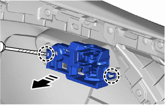
Protective Tape Remove in this Direction Using a thin-bladed screwdriver, detach the claw and remove the front door inside handle sub-assembly LH from the front door trim board sub-assembly LH.
Tech Tips
Tape the thin-bladed screwdriver tip before use.
-
-
REMOVE SEAT MEMORY SWITCH (w/ Seat Memory Switch)
-
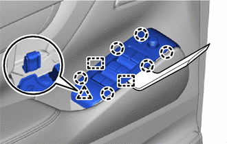
REMOVE FRONT DOOR TRIM ORNAMENT SUB-ASSEMBLY LH (w/o Seat Memory Switch)
-
Remove in this Direction Remove the 9 screws.
-
Detach the guide and remove the front door trim ornament sub-assembly LH as shown in the illustration.
-
-
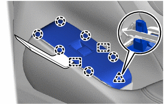
REMOVE FRONT NO. 2 DOOR TRIM ORNAMENT BASE (w/ Seat Memory Switch)
-
Remove in this Direction Remove the 9 screws.
-
Detach the guide and remove the front No. 2 door trim ornament base together with the No. 2 side trim base plate as shown in the illustration.
-
-
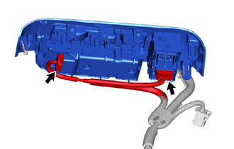
REMOVE NO. 2 SIDE TRIM BASE PLATE (w/ Seat Memory Switch)
-
Remove in this Direction Detach the claw and remove the No. 2 side trim base plate from the front No. 2 door trim ornament base as shown in the illustration.
-
-
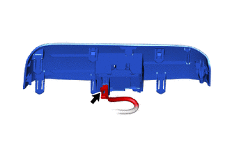
REMOVE FRONT DOOR SPEAKER GRILLE SUB-ASSEMBLY LH (w/ Seat Memory Switch)
-
Remove the 4 screws and 4 spacers.
-
Detach the claw and remove the front door speaker grille sub-assembly LH from the front door trim board sub-assembly LH.
-
-
REMOVE FRONT DOOR INNER GLASS WEATHERSTRIP LH
-
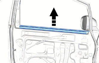
Remove in this Direction Remove the front door inner glass weatherstrip LH as shown in the illustration.
-
-
REMOVE DOOR SIDE AIR BAG SENSOR LH
-
REMOVE OUTER MIRROR INSTALL HOLE COVER LH
-
REMOVE OUTER MIRROR PROTECTOR
-
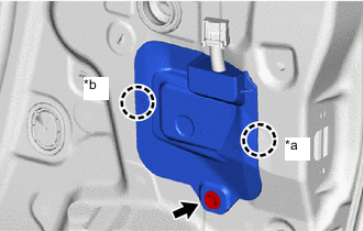
*a Claw A *b Claw B Remove the screw.
-
Detach the claw A.
-
Detach the claw B and remove the outer mirror protector.
-
-
REMOVE OUTER REAR VIEW MIRROR ASSEMBLY LH
-
REMOVE OUTER MIRROR CONTROL ECU ASSEMBLY (w/ Reverse Shift-linked Mirror)
-
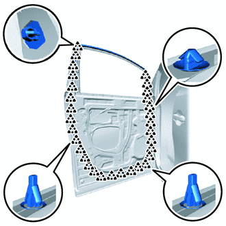
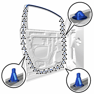
REMOVE FRONT DOOR SERVICE HOLE COVER LH
-
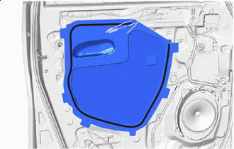

Butyl Tape Remove the front door service hole cover LH.
Note
Remove any remaining butyl tape from the front door panel LH.
-
-
REMOVE FRONT NO. 1 SPEAKER ASSEMBLY
-
REMOVE FRONT DOOR FRONT WINDOW FRAME MOULDING LH
-
REMOVE FRONT DOOR REAR WINDOW FRAME MOULDING LH
-
REMOVE FRONT DOOR GLASS SUB-ASSEMBLY LH
-
Connect the multiplex network master switch assembly.
-
Remove the hole plug.
-
Connect the cable to the negative (-) battery terminal.
-
Move the front door window regulator sub-assembly LH so that the front door glass sub-assembly LH bolts can be seen.
-
Disconnect the cable from the negative (-) battery terminal.
CAUTION:
-
Wait at least 90 seconds after disconnecting the cable from the negative (-) battery terminal to disable the SRS system.
-
If the airbag deploys for any reason, it may cause a serious accident.
Note
When disconnecting the cable, some systems need to be initialized after the cable is reconnected.
-
-
Disconnect the multiplex network master switch assembly.
-
Remove the 2 bolts.
-
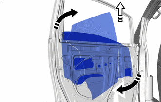
Remove in this Direction (1) Remove in this Direction (2) Remove the front door glass sub-assembly LH as shown in the illustration.
Note
Do not damage the front door glass sub-assembly LH.
-
-
REMOVE FRONT DOOR GLASS RUN LH
-
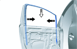
Remove in this Direction (1) Remove in this Direction (2) w/ Upper Window Frame Moulding:
Remove the front door glass run LH as shown in the illustration.
-
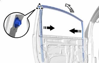
Remove in this Direction (1) Remove in this Direction (2) w/o Upper Window Frame Moulding:
Detach the clip and remove the front door glass run LH as shown in the illustration.
-
-
REMOVE FRONT DOOR WINDOW REGULATOR SUB-ASSEMBLY LH
-
Disconnect the connector.
-
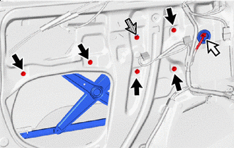
Bolt Connector 
Temporarily Bolt Loosen the temporarily bolt.
Note
Do not remove the temporarily bolt. If the temporarily bolt is removed, the front door window regulator sub-assembly LH may fall and become damaged.
-
Remove the 5 bolts and front door window regulator sub-assembly LH.
-
Remove the temporarily bolt from the front door window regulator sub-assembly LH.
-
-
REMOVE POWER WINDOW REGULATOR MOTOR ASSEMBLY LH
-
REMOVE FRONT DOOR REAR LOWER FRAME SUB-ASSEMBLY LH
-
Remove the bolt.
-
Detach the guide and remove the front door rear lower frame sub-assembly LH.
-
-
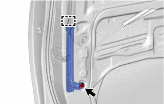
REMOVE FRONT DOOR OUTSIDE HANDLE COVER WITH LOCK CYLINDER ASSEMBLY (for Driver Side)
-
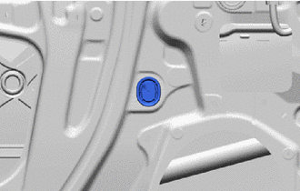
*1 Hole Plug Remove in this Direction Remove the hole plug.
-
Using a T30 "TORX" socket wrench, loosen the screw and remove the front door outside handle cover with lock cylinder assembly.
-
-
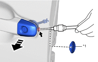
REMOVE FRONT DOOR OUTSIDE HANDLE COVER LH (for Driver Side)
-
Protective Tape Remove in this Direction Using a thin-bladed screwdriver, detach the claw and guide and remove the front door outside handle cover LH as shown in the illustration.
Tech Tips
Tape the thin-bladed screwdriver tip before use.
-
-
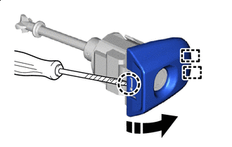
REMOVE FRONT DOOR OUTSIDE HANDLE COVER RH (for Front Passenger Side)
-
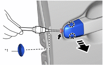
*1 Hole Plug Remove in this Direction Remove the hole plug.
-
Using a T30 "TORX" socket wrench, loosen the screw.
-
Detach the claw and remove the front door outside handle cover LH as shown in the illustration.
-
-
REMOVE FRONT DOOR OUTSIDE HANDLE ASSEMBLY LH
-
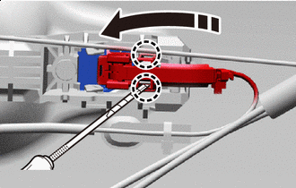
Protective Tape Remove in this Direction Using a thin-bladed screwdriver, detach the claw and open the connector cover as shown in the illustration.
Tech Tips
Tape the thin-bladed screwdriver tip before use.
-
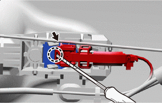
Protective Tape Remove in this Direction Using a thin-bladed screwdriver, detach the claw and disconnect the connector and connector cover as shown in the illustration.
Tech Tips
Tape the thin-bladed screwdriver tip before use.
-
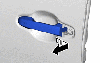
Remove in this Direction Remove the front door outside handle assembly LH as shown in the illustration.
-
-
REMOVE FRONT DOOR FRONT OUTSIDE HANDLE PAD
-
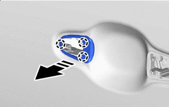
Remove in this Direction Detach the claw and remove the front door front outside handle pad.
-
-
REMOVE FRONT DOOR REAR OUTSIDE HANDLE PAD
-
Remove in this Direction Detach the claw and remove thefront door rear outside handle pad.
-
-
REMOVE FRONT DOOR WITH MOTOR LOCK ASSEMBLY LH
-
REMOVE FRONT DOOR LOCK COVER SUB-ASSEMBLY LH
-
REMOVE FRONT DOOR LOCK REMOTE CONTROL CABLE ASSEMBLY LH
-
REMOVE FRONT DOOR INSIDE LOCKING CABLE ASSEMBLY LH
-
REMOVE FRONT DOOR OUTSIDE HANDLE FRAME SUB-ASSEMBLY LH
-
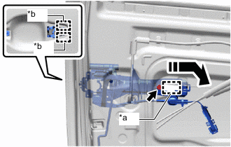
*a Grommet *b Guide Remove in this Direction Using a T30 "TORX" socket wrench, loosen the screw.
-
Detach the grommet and guide and remove the front door outside handle frame sub-assembly LH together with the wire harness.
-
*a Clamp *b Guide Detach the clamp and guide, disconnect the wire harness and remove the front door outside handle frame sub-assembly LH.
-
-
REMOVE FRONT DOOR LOCK OPEN ROD LH
-
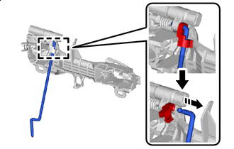
Remove in this Direction Detach the snap and remove the front door lock open rod LH from the front door outside handle sub-assembly LH as shown in the illustration.
-
-
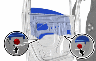
REMOVE FRONT DOOR CHECK ASSEMBLY LH
-
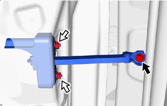
Bolt Nut Remove the bolt, 2 nuts and front door check assembly LH.
-
-
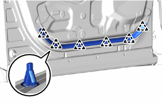
REMOVE FRONT DOOR PANEL CUSHION
-
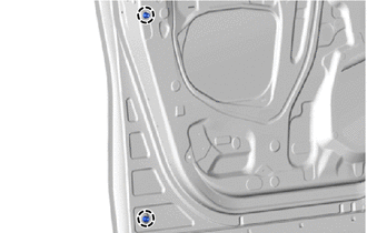
Detach the claw and remove the 2 front door panel cushions.
-
-
REMOVE FRONT DOOR WEATHERSTRIP LH
-
w/ Upper Window Frame Moulding:
Using a clip remover, detach the clip and remove the front door weatherstrip LH.
-
w/o Upper Window Frame Moulding:
Using a clip remover, detach the clip and remove the front door weatherstrip LH.
-
-
REMOVE FRONT DOOR NO. 2 WEATHERSTRIP LH
-
Using a clip remover, detach the clip and remove the front door No. 2 weatherstrip LH.
-
-
REMOVE FRONT DOOR OUTER GLASS WEATHERSTRIP LH
-
REMOVE FRONT DOOR UPPER WINDOW FRAME MOULDING LH (w/ Upper Window Frame Moulding)
-
REMOVE NO. 2 BLACK OUT TAPE LH
-
REMOVE NO. 1 BLACK OUT TAPE LH
-
REMOVE FRONT DOOR MUDGUARD LH