BACK DOOR DISASSEMBLY
CAUTION / NOTICE / HINT
The necessary procedures(adjustment, calibration, initialization, or registration) that must be performed after parts are removed, installed or replaced during the back door disassembly/reassembly are shown below.
| Replacement Part or Procedure | Necessary Procedures | Effects/Inoperative when not Performed | Link |
|---|---|---|---|
|
Television camera view adjustment | Panoramic view monitor system |
Note
For vehicles with a power back door, check that the power back does not operate before proceeding with work.
PROCEDURE
-
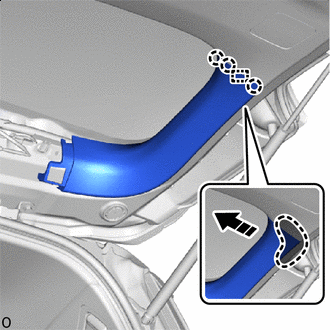
REMOVE CENTER BACK DOOR GARNISH
-
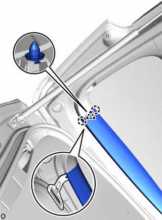
Using moulding remover C, detach the claw and clip as shown in the illustration.
-
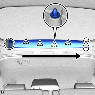

Place Hands Here 
Order of Removal Detach the clip, claw and remove the center back door garnish as shown in the illustration.
-
-
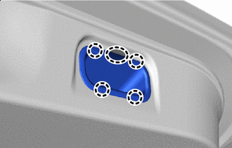
REMOVE BACK DOOR SERVICE HOLE COVER LH (w/ Power Back Door)
-
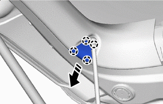

Remove in this Direction Detach the claw and remove the back door service hole cover LH.
-
-
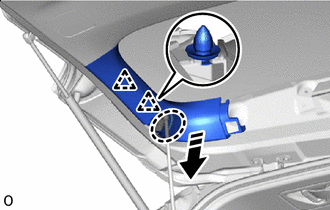
REMOVE BACK DOOR SIDE GARNISH LH (w/o Power Back Door)
-
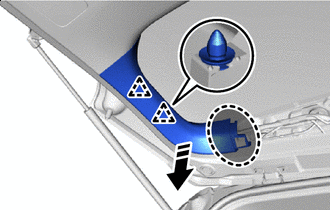
Place Hands Here Remove in this Direction Detach the clip.
-
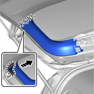
Place Hands Here Remove in this Direction Detach the claw, guide and remove the back door side garnish LH as shown in the illustration.
-
-
REMOVE BACK DOOR SIDE GARNISH LH (w/ Power Back Door)
-
Place Hands Here Remove in this Direction Detach the clip.
-
Place Hands Here Remove in this Direction Detach the claw, guide and remove the back door side garnish LH as shown in the illustration.
-
-
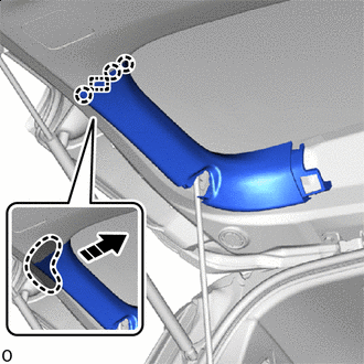
REMOVE BACK DOOR SIDE GARNISH RH
-
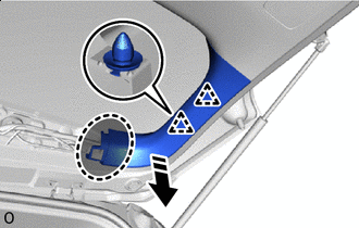
Place Hands Here Remove in this Direction Detach the clip.
-
Place Hands Here Remove in this Direction Detach the claw, guide and remove the back door side garnish RH as shown in the illustration.
-
-
REMOVE BACK DOOR INSIDE HANDLE
-
Place Hands Here Place your hand at the position shown in the illustration, detach the claw and remove the back door inside handle.
-
-
REMOVE SWITCH BEZEL (w/ Power Back Door)
-
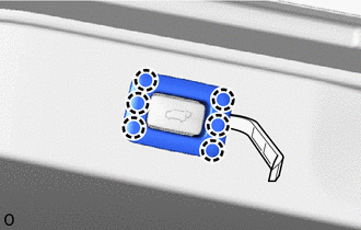
Using moulding remover A, detach the claw and remove the switch bezel as shown in the illustration.
-
-
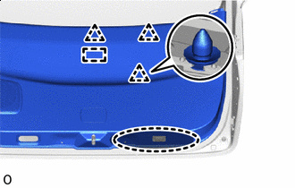
REMOVE BACK DOOR TRIM BOARD ASSEMBLY
-
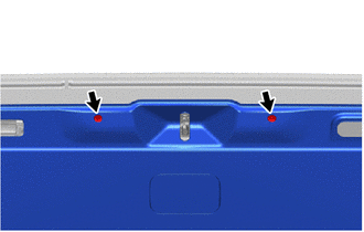
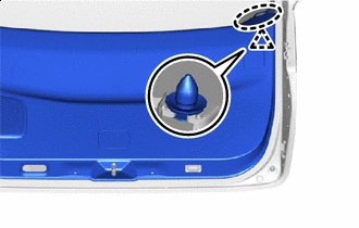
Remove the 2 clips.
-
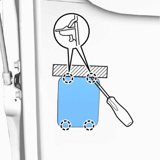

Protective Tape Apply protective tape as shown in the illustration.
Tech Tips
Use the same procedure for the other side.
-
Using a thin-bladed screwdriver, detach the claw and remove the back door service hole cover.
Tech Tips
-
Tape the thin-bladed screwdriver tip before use.
-
Use the same procedure to remove the back door service hole cover on the other side.
-
-
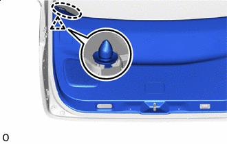
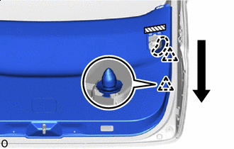
Place Hands Here Place your hand at the position shown in the illustration, detach the clip.
-
Place Hands Here Order of Removal Place your hand at the position shown in the illustration, detach the clip.
-
Order of Removal Detach the clip as shown in the illustration.
-
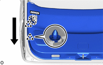
Place Hands Here Place your hand at the position shown in the illustration, detach the clip.
-
Place Hands Here Order of Removal Place your hand at the position shown in the illustration, detach the clip.
-
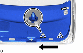
Order of Removal Detach the clip.
-
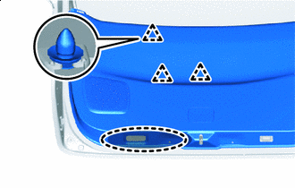
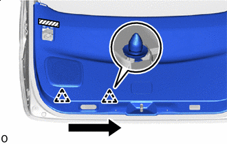
Insert hand here Detach the clip as shown in the illustration.
-
Insert hand here Detach the clip, guide and remove the back door trim board assembly as shown in the illustration.
-
-
REMOVE BACK DOOR LOCK ASSEMBLY
-
REMOVE BACK DOOR CONTROL SWITCH
-
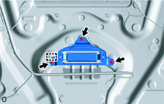
DISCONNECT POWER BACK DOOR ROD (w/ Power Back Door)
-
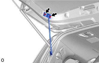
Remove the 2 bolts and disconnect the power back door rod.
-
-
REMOVE BACK DOOR SIDE MALE STOPPER LH
-
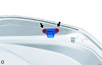
Remove the 2 bolts and back door side male stopper LH.
-
-
REMOVE BACK DOOR SIDE MALE STOPPER RH
Tech Tips
Use the same procedure described for the LH side.
-
REMOVE POWER BACK DOOR SENSOR ASSEMBLY LH (w/ Power Back Door)
-
REMOVE POWER BACK DOOR SENSOR ASSEMBLY RH (w/ Power Back Door)
Tech Tips
Use the same procedure described for the LH side.
-
REMOVE BACK DOOR PANEL CUSHION
Tech Tips
Use the same procedure for both back door panel cushions.
-
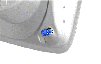
Detach the claw and remove the back door panel cushion.
-
-
REMOVE REAR NO. 3 SPEAKER ASSEMBLY (w/ Back Door Speaker)
-
REMOVE REAR SPOILER
-
REMOVE REAR SPOILER SEAL
-
REMOVE REAR WIPER ARM AND BLADE ASSEMBLY
-
REMOVE NO. 1 REAR SPOILER COVER
-
REMOVE REAR WIPER MOTOR GROMMET
-
REMOVE WINDSHIELD WIPER MOTOR ASSEMBLY
-
REMOVE BACK DOOR OUTSIDE GARNISH SUB-ASSEMBLY
-
for ALPHARD:
-
for VELLFIRE:
-
-
REMOVE BACK DOOR OPENER SWITCH ASSEMBLY
-
REMOVE BACK DOOR WEIGHT (for 2AR-FE)
-
Remove the 3 bolts.
-
Detach the guide and remove the back door weight.
-
-
REMOVE LICENSE PLATE LIGHT ASSEMBLY
-
REMOVE REAR LIGHT ASSEMBLY LH (for ALPHARD)
-
REMOVE REAR LIGHT ASSEMBLY RH (for ALPHARD)
Tech Tips
Use the same procedure described for the LH side.
-
REMOVE REAR LIGHT ASSEMBLY LH (for VELLFIRE)
-
REMOVE REAR LIGHT ASSEMBLY RH (for VELLFIRE)
Tech Tips
Use the same procedure described for the LH side.
-
REMOVE REAR TELEVISION CAMERA ASSEMBLY (w/ Panoramic View Monitor System)
-
REMOVE BACK DOOR GARNISH COVER (w/o Panoramic View Monitor System)
-
Remove the 2 screws and back door garnish cover.
-