POWER SLIDE DOOR MOTOR INSTALLATION
CAUTION / NOTICE / HINT
Tech Tips
-
Use the same procedure for the RH and LH sides.
-
The procedure listed below is for the LH side.
-
A bolt without a torque specification is shown in the standard bolt chart.
PROCEDURE
-
INSTALL SLIDE DOOR MOTOR UNIT LH
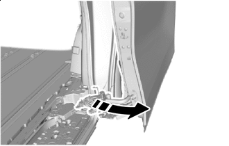

Pull Direction
-
Pull out the lower part of the slide door toward the outside of the vehicle as shown in the illustration so that the slide door motor unit LH can be installed.
Note
-
To prevent the slide door LH from being dropped, deformed or damaged, make sure that there are enough people available to assist when performing this operation.
-
Do not pull the slide door LH excessively. Otherwise, the slide door roller assembly LH or upper slide door rail LH may be deformed or damaged.
-
-
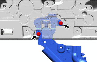
Temporarily install the slide door motor unit LH as shown in the illustration.
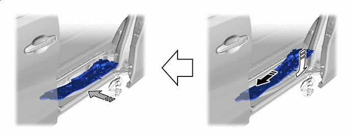
Installation Direction (1) 
Installation Direction (2) 
Installation Direction (3) - - -
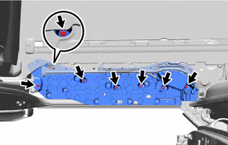
Install the slide door motor unit LH with the 7 bolts.
- Torque:
- 7.8 N*m { 80 kgf*cm, 69 in.*lbf }
-
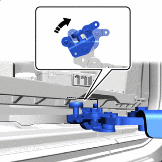
Clockwise Rotate the roller part of the lower slide door roller arm LH clockwise to connect the lower slide door roller arm LH to the cutout of the slide door motor unit LH.
Note
-
Support the lower portion of the slide door LH when connecting the lower slide door LH, as the slide door LH becomes unstable.
-
Work with 2 or more persons when connecting the slide door LH in order to prevent deformation and damage.
-
-
Move the slide door LH so that the bolt holes are visible.
-
Connect the lower slide door roller arm LH to the slide door motor unit LH with the 2 bolts.
- Torque:
- 7.8 N*m { 80 kgf*cm, 69 in.*lbf }
-
-
INSTALL LOWER SLIDE DOOR RAIL PLATE LH
-
CONNECT REAR DOOR WIRE LH
-
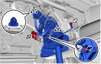

Bolt 
Ground Bolt 
Connector Attach the clip.
-
Connect the ground wire with the ground bolt.
- Torque:
- 8.0 N*m { 82 kgf*cm, 71 in.*lbf }
-
Install the bolt to connect the rear door wire LH.
- Torque:
- 8.0 N*m { 82 kgf*cm, 71 in.*lbf }
-
Connect the 2 connectors.
-
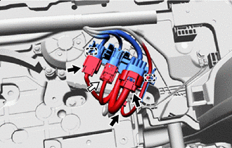
Airbag Connector Attach the clamp to connect the connector holder.
-
Before connecting the airbag connector, check that the position of the housing lock is correct as shown in the illustration.
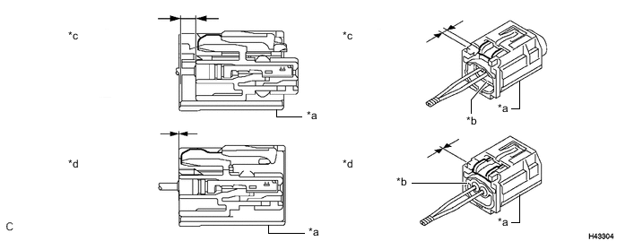
*a CPA *b Housing *c Correct *d Incorrect -
Connect the airbag connector.
Note
When connecting any airbag connector, take care not to damage the airbag wire harness.
-
While holding the CPA, be sure to engage the connectors until they are locked and check that the CPA is in its original position (when locking, make sure that a click sound can be heard).
Note
Do not push down the upper part of the CPA shown in the illustration when connecting the airbag connector.
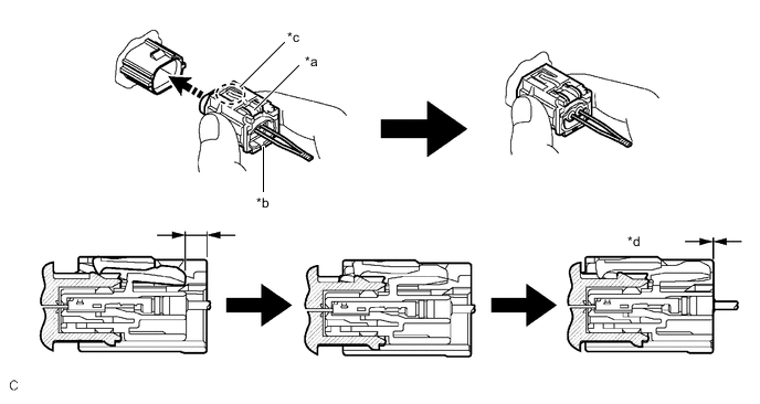
*a Housing Lock *b CPA *c CPA Upper Part *d Connection is Completed Connect Direction - -
-
-
Connect each connector.
-
-
INSTALL REAR SIDE STEP SUPPORT LH
-
INSTALL REAR DOOR SCUFF PLATE LH
-
CONNECT CABLE TO NEGATIVE BATTERY TERMINAL
Note
When disconnecting the cable, some systems need to be initialized after the cable is reconnected.
-
CHECK SRS WARNING LIGHT
-
PERFORM DIAGNOSTIC SYSTEM CHECK
-
CHECK SLIDE DOOR CLOSER SYSTEM
-
CHECK POWER SLIDE DOOR SYSTEM