POWER BACK DOOR SYSTEM TERMINALS OF ECU
-
CHECK BACK DOOR MOTOR UNIT
-
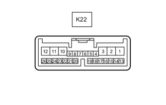
Disconnect the K22 back door motor unit connector.
-
Measure the voltage and resistance according to the value(s) in the table below.
Tech Tips
Measure the values on the wire harness side with the connector disconnected.
Terminal No. (Symbol) Wiring Color Terminal Description Condition Specified Condition K22-10 (ECUB) - Body ground G - Body ground Battery power supply Always 11 to 14 V K22-8 (IG) - Body ground Y - Body ground IG power supply Engine switch on (IG) 11 to 14 V Engine switch off Below 1 V K22-12 (B) - Body ground R - Body ground Battery power supply Always 11 to 14 V K22-11 (GND) - Body ground W-B - Body ground Body ground Always Below 1 Ω -
Reconnect the K22 back door motor unit connector.
-
Measure the voltage and waveform according to the value(s) in the table below.
Terminal No. (Symbol) Wiring Color Terminal Description Condition Specified Condition K22-2 (DC+) - K22-1 (DC-) G - R Back door lock assembly (back door lock motor) circuit Back door lock motor operating 11 to 14 V Back door lock motor not operating Below 1 V K22-4 (DS1) - Body ground G - Body ground Back door control switch signal Back door control switch on Below 1 V Back door control switch off Pulse generation K22-26 (BZR+) - Body ground B - Body ground Wireless door lock buzzer signal Power back door warning buzzer sounding Pulse generation Power back door warning buzzer not sounding Below 1 V K22-15 (OSL) - K22-14 (OSE) BR - B Power back door sensor assembly LH signal Power back door sensor assembly LH not pressed 4 to 6 V Power back door sensor assembly LH pressed Below 1 V K22-13 (OSR) - K22-14 (OSE) W - B Power back door sensor assembly RH signal Power back door sensor assembly RH not pressed 4 to 6 V Power back door sensor assembly RH pressed Below 1 V K22-17 (MSW) - Body ground R - Body ground Power slide door main switch signal Power slide door main switch on Below 1.5 V Power slide door main switch off 6 V or higher
-
-
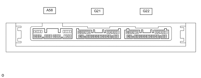
CHECK CERTIFICATION ECU (SMART KEY ECU ASSEMBLY)
-
Disconnect the G22 certification ECU (smart key ECU assembly) connector.
-
Measure the voltage and resistance according to the value(s) in the table below.
Tech Tips
Measure the values on the wire harness side with the connector disconnected.
Terminal No. (Symbol) Wiring Color Terminal Description Condition Specified Condition G22-10 (+B) - Body ground GR - Body ground Battery power supply Always 11 to 14 V G22-11 (E) - Body ground W-B - Body ground Body ground Always Below 1 Ω -
Reconnect the G22 certification ECU (smart key ECU assembly) connector.
-
Measure the waveform according to the value(s) in the table below.
Terminal No. (Symbol) Wiring Color Terminal Description Condition Specified Condition G21-5 (TSW5) - G22-11 (E) G - W-B Back door opener switch assembly signal Back door opener switch assembly (open switch) off → on Pulse generation (See waveform 1)
-
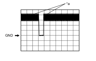
*a In actuality, sampling is being performed Using an oscilloscope, check waveform 1.
Waveform 1 (Reference) Item Content Terminal No. (Symbol) G21-5 (TSW5) - G22-11 (E) Tool Setting 2 V/DIV., 500 ms./DIV. Condition Back door opener switch assembly (open switch) off → on
-
-
-
CHECK MAIN BODY ECU (MULTIPLEX NETWORK BODY ECU) AND JUNCTION BLOCK ASSEMBLY LH
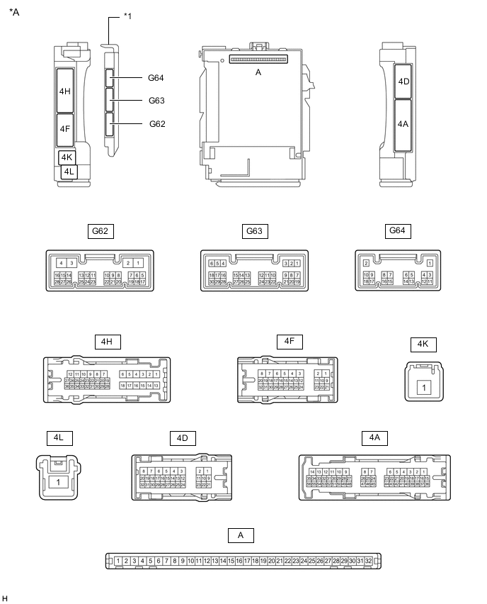
*A Main Body ECU (Multiplex Network Body ECU) with 3 connectors - - *1 Main Body ECU (Multiplex Network Body ECU) - - 
*A Main Body ECU (Multiplex Network Body ECU) with 2 connectors - - *1 Main Body ECU (Multiplex Network Body ECU) - -
-
Remove the main body ECU (multiplex network body ECU).
-
Connect the junction block assembly LH connectors.
-
Measure the voltage and resistance according to the value(s) in the table below.
Terminal No. (Symbol) Wiring Color Terminal Description Condition Specified Condition A-31 (BECU) - Body ground None - Body ground Battery power supply Always 11 to 14 V A-30 (ACC) - Body ground None - Body ground ACC power supply Engine switch on (ACC) 11 to 14 V Engine switch off Below 1 V A-32 (IG) - Body ground None - Body ground IG power supply Engine switch on (IG) 11 to 14 V Engine switch off Below 1 V A-11 (GND1) - Body ground None - Body ground Body ground Always Below 1 Ω -
Install the main body ECU (multiplex network body ECU).
-
Measure the voltage and waveform according to the value(s) in the table below.
Terminal No. (Symbol) Wiring Color Terminal Description Condition Specified Condition G62-5 (PBDS) - Body ground G - Body ground Map light assembly (power back door switch) signal Map light assembly (power back door switch) off Pulse generation Map light assembly (power back door switch) on Below 1 V
-