POWER SLIDE DOOR SYSTEM Only One-touch Function does not Operate (LH Door)
DESCRIPTION
The slide door motor unit LH (slide door ECU LH) receives signals from the rear door outside handle cover LH (one-touch switch) and performs power slide door open or close operations.
WIRING DIAGRAM
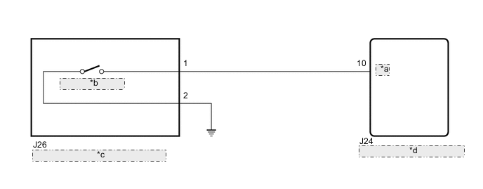
| *a | HSW |
| *b | One-touch Switch |
| *c | Rear Door Outside Handle Cover LH |
| *d | Slide Door Motor Unit LH (Slide Door ECU LH) |
CAUTION / NOTICE / HINT
Note
Check that the "One Touch Open/Close SW Operation Setting (RL)" customization setting is set to "Short Push (0.3s), Middle Push (0.5s) or Long Push (0.8s)".
PROCEDURE
-
CHECK SMART ENTRY AND START SYSTEM (for Entry Function)
-
Check the door lock/unlock operation via the smart operation.
OK Smart entry function operates normally. Result Proceed to OK NG
NG 
GO TO SMART ENTRY AND START SYSTEM (for Entry Function) Click here
OK 
-
-
READ VALUE USING GTS
-
Read the Data List according to the display on the GTS.
Body Electrical > Rear Left Door > Data ListTester Display Measurement Item Normal Condition Reference Value Diagnostic Note One Touch Open/Close Switch One-touch switch signal ON or OFF ON: One-touch switch on
OFF: One-touch switch off
-
Body Electrical > Rear Left Door > Data ListTester Display One Touch Open/Close Switch OK On the GTS screen, ON or OFF is displayed accordingly. Result Proceed to OK NG
OK
REPLACE SLIDE DOOR MOTOR UNIT LH Click here
NG
-
-
INSPECT REAR DOOR OUTSIDE HANDLE COVER LH
-
Remove the rear door outside handle cover LH.
-
Inspect the rear door outside handle cover LH.
Result Proceed to OK NG
NG
REPLACE REAR DOOR OUTSIDE HANDLE COVER LH Click here
OK
-
-
CHECK HARNESS AND CONNECTOR (REAR DOOR OUTSIDE HANDLE COVER LH - SLIDE DOOR MOTOR UNIT LH AND BODY GROUND)
-
Disconnect the J26 rear door outside handle cover LH (one-touch switch) connector.
-
Disconnect the J24 slide door motor unit LH (slide door ECU LH) connector.
-
Measure the resistance according to the value(s) in the table below.
Standard Resistance Tester Connection Condition Specified Condition J26-1 - J24-10 (HSW) Always Below 1 Ω J26-2 - Body ground Always Below 1 Ω J26-1 or J24-10 (HSW) - Body ground Always 10 kΩ or higher Result Proceed to OK NG
OK
REPLACE SLIDE DOOR MOTOR UNIT LH Click here
NG
REPAIR OR REPLACE HARNESS OR CONNECTOR
-