POWER SLIDE DOOR SYSTEM Assist Function does not Operate (Normal Operation via Door Control Switch) (RH Door)
DESCRIPTION
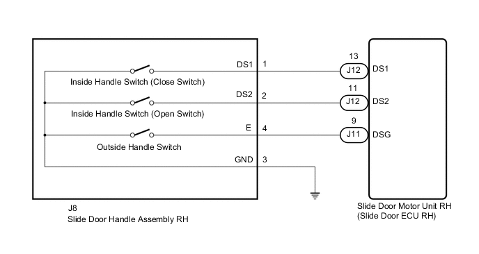
The slide door motor unit RH (slide door ECU RH) receives signals from the inside handle or outside handle in the slide door handle assembly RH and performs power slide door open or close operations.
WIRING DIAGRAM
PROCEDURE
-
READ VALUE USING GTS
-
Read the Data List according to the display on the GTS.
Body Electrical > Rear Right Door > Data ListTester Display Measurement Item Normal Condition Reference Value Diagnostic Note Handle Switch1 Inside handle switch (close switch) signal ON or OFF ON: Slide door inside handle close operation performed (inside handle switch [close switch] on)
OFF: Slide door inside handle operation not performed or open operation performed (inside handle switch [close switch] off)
- Handle Switch2 Inside handle switch (open switch) signal ON or OFF ON: Slide door inside handle open operation performed (inside handle switch [open switch] on)
OFF: Slide door inside handle operation not performed or close operation performed (inside handle switch [open switch] off)
- Outside PSD Switch Status of outside handle (outside handle switch) ON or OFF ON: Outside handle operated (outside handle switch on)
OFF: Outside handle not operated (outside handle switch off)
-
Body Electrical > Rear Right Door > Data ListTester Display Handle Switch1 Handle Switch2 Outside PSD Switch OK On the GTS screen, ON or OFF is displayed accordingly. Result Proceed to OK NG
OK 
REPLACE SLIDE DOOR MOTOR UNIT RH Click here
NG 
-
-
INSPECT SLIDE DOOR HANDLE ASSEMBLY RH
-
Remove the slide door handle assembly RH.
-
Inspect the slide door handle assembly RH.
Result Proceed to OK NG
NG
REPLACE SLIDE DOOR HANDLE ASSEMBLY RH Click here
OK
-
-
CHECK HARNESS AND CONNECTOR (SLIDE DOOR HANDLE ASSEMBLY RH - SLIDE DOOR MOTOR UNIT RH AND BODY GROUND)
-
Disconnect the J8 slide door handle assembly RH connector.
-
Disconnect the J11 and J12 slide door motor unit RH (slide door ECU RH) connectors.
-
Measure the resistance according to the value(s) in the table below.
Standard Resistance Tester Connection Condition Specified Condition J8-1 (DS1) - J12-13 (DS1) Always Below 1 Ω J8-2 (DS2) - J12-11 (DS2) Always Below 1 Ω J8-4 (E) - J11-9 (DSG) Always Below 1 Ω J8-3 (GND) - Body ground Always Below 1 Ω J8-1 (DS1) or J12-13 (DS1) - Body ground Always 10 kΩ or higher J8-2 (DS2) or J12-11 (DS2) - Body ground Always 10 kΩ or higher J8-4 (E) or J11-9 (DSG) - Body ground Always 10 kΩ or higher Result Proceed to OK NG
OK
REPLACE SLIDE DOOR MOTOR UNIT RH Click here
NG
REPAIR OR REPLACE HARNESS OR CONNECTOR
-