POWER SLIDE DOOR SYSTEM TERMINALS OF ECU
-
SLIDE DOOR MOTOR UNIT RH (SLIDE DOOR ECU RH)
-
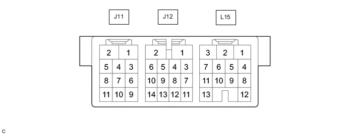
Disconnect the J11, J12 and L15 slide door motor unit RH (slide door ECU RH) connectors.
-
Measure the voltage and resistance according to the value(s) in the table below.
Tester Connection Wiring Color Terminal Description Condition Specified Condition L15-1 (B) - Body ground R - Body ground Power supply Always 11 to 14 V L15-5 (ECUB) - Body ground LG - Body ground Power supply Always 11 to 14 V L15-3 (GND) - Body ground W-B - Body ground Ground Always Below 1 Ω L15-9 (MSW) - Body ground L - Body ground Power slide door main switch signal Power slide door main switch on → off Below 1 Ω → 10 kΩ or higher J11-10 (HSW) - Body ground P - Body ground One-touch switch signal One-touch switch on → off Below 1 Ω → 10 kΩ or higher J11-7 (OS) - J11-4 (OSG) GR - W Power slide door sensor assembly RH signal Power slide door sensor assembly RH pushed → not pushed Below 100 Ω → 1 kΩ or higher J12-2 (HAF) - L15-3 (GND) P - W-B Half-latch switch input Slide door RH open (half-latch switch on) → door ajar (half-latch switch off)
Tech Tips
For details regarding the on/off operation of the half-latch switch, refer to the timing chart in the system description.
Below 1 Ω → 10 kΩ or higher J11-6 (FUL) - L15-3 (GND) BR - W-B Full-latch switch input Slide door RH open → fully closed (full-latch switch on) → fully closed (full-latch switch off)
Tech Tips
For details regarding the on/off operation of the full-latch switch, refer to the timing chart in the system description.
Below 1 Ω → 10 kΩ or higher J12-4 (POL) - L15-3 (GND) G - W-B Pawl switch input Slide door RH open → fully closed
Tech Tips
For details regarding the on/off operation of the pawl switch, refer to the timing chart in the system description.
10 kΩ or higher → (Below 1 Ω → 10 kΩ or higher) J11-9 (DSG) - L15-3 (GND) R - W-B Outside handle switch signal Outside handle not operated → outside handle operated 10 kΩ or higher → Below 1 Ω J12-11 (DS2) - L15-3 (GND) LG - W-B Inside handle switch (open switch) signal Inside handle not operated → inside handle operated to open side 10 kΩ or higher → Below 1 Ω J12-13 (DS1) - L15-3 (GND) L - W-B Inside handle switch (close switch) signal Inside handle not operated → inside handle operated to close side 10 kΩ or higher → Below 1 Ω -
Reconnect the J11, J12 and L15 slide door motor unit RH (slide door ECU RH) connectors.
-
Measure the voltage and waveform according to the value(s) in the table below.
Tester Connection Wiring Color Terminal Description Condition Specified Condition J11-1 (DC+) - L15-3 (GND) L - W-B Slide door closer output (close rotation) Slide door RH open → ajar → motor normal rotation operation → reverse operation → operation complete (fully closed condition) Below 1 V → Below 1 V → 11 to 14 V → Below 1 V → Below 1 V Slide door RH fully closed → slide door open signal input → motor reverse operation (latch release) → motor stops → motor normal operation → operation complete (fully open condition) Below 1 V → Below 1 V → Below 1 V → Below 1 V → 11 to 14 V → Below 1 V J11-2 (DC-) - L15-3 (GND) G - W-B Slide door closer output (release rotation) Slide door RH open → ajar → motor normal rotation operation → reverse operation → operation complete (fully closed condition) Below 1 V → Below 1 V → Below 1 V → 11 to 14 V → Below 1 V Slide door RH fully closed → slide door open signal input → motor reverse operation (latch release) → motor stops → motor normal operation → operation complete (fully open condition) Below 1 V → Below 1 V → 11 to 14 V → Below 1 V → Below 1 V → Below 1 V J12-6 (P) - L15-3 (GND) B - W-B Neutral position close switch input Slide door RH open → ajar → motor normal rotation operation in progress → reverse operation → operation complete (fully closed condition)
Tech Tips
For details regarding the on/off operation of the neutral position close switch, refer to the timing chart in the system description.
11 to 14 V → 11 to 14 V → Below 1 V → Below 1 V → 11 to 14 V J12-9 (SPD) - L15-3 (GND) R - W-B Neutral position release switch input Slide door RH closed → motor reverse operation in progress → motor normal operation → operation complete (fully open condition)
Tech Tips
For details regarding the on/off operation of the neutral position release switch, refer to the timing chart in the system description.
11 to 14 V → Below 1 V → Below 1 V → 11 to 14 V J12-10 (BZR+) - L15-3 (GND) V - W-B Power slide door warning buzzer RH signal Power slide door warning buzzer RH sounds Waveform
-
-
SLIDE DOOR MOTOR UNIT LH (SLIDE DOOR ECU LH)
-
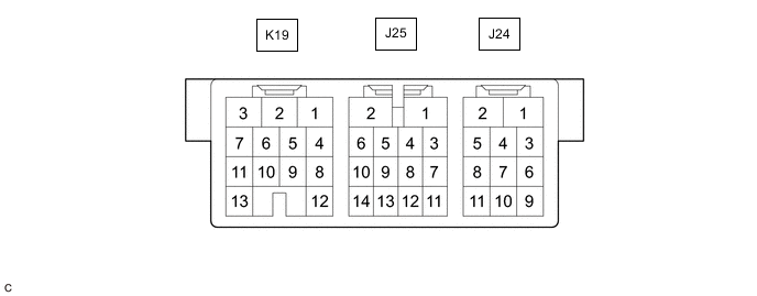
Disconnect the J24, J25 and K19 slide door motor unit LH (slide door ECU LH) connectors.
-
Measure the voltage and resistance according to the value(s) in the table below.
Tester Connection Wiring Color Terminal Description Condition Specified Condition K19-1 (B) - Body ground L - Body ground Power supply Always 11 to 14 V K19-5 (ECUB) - Body ground G - Body ground Power supply Always 11 to 14 V K19-3 (GND) - Body ground W-B - Body ground Ground Always Below 1 Ω K19-9 (MSW) - Body ground B - Body ground Power slide door main switch or slide door half open stopper control assembly signal Power slide door main switch and slide door half open stopper control assembly on → Power slide door main switch or slide door half open stopper control assembly off Below 1 Ω → 10 kΩ or higher J24-10 (HSW) - Body ground P - Body ground One-touch switch signal One-touch switch on → off Below 1 Ω → 10 kΩ or higher J24-7 (OS) - J24-4 (OSG) GR - W Power slide door sensor assembly LH signal Power slide door sensor assembly LH pushed → not pushed Below 100 Ω → 1 kΩ or higher J25-2 (HAF) - K19-3 (GND) P - W-B Half-latch switch input Slide door LH open (half-latch switch on) → door ajar (half-latch switch off)
Tech Tips
For details regarding the on/off operation of the half-latch switch, refer to the timing chart in the system description.
Below 1 Ω → 10 kΩ or higher J24-6 (FUL) - K19-3 (GND) BR - W-B Full-latch switch input Slide door LH open → fully closed (full-latch switch on) → fully closed (full-latch switch off)
Tech Tips
For details regarding the on/off operation of the full-latch switch, refer to the timing chart in the system description.
Below 1 Ω → 10 kΩ or higher J25-4 (POL) - K19-3 (GND) G - W-B Pawl switch input Slide door LH open → fully closed
Tech Tips
For details regarding the on/off operation of the pawl switch, refer to the timing chart in the system description.
10 kΩ or higher → (Below 1 Ω → 10 kΩ or higher) J24-9 (DSG) - K19-3 (GND) R - W-B Outside handle switch Outside handle not operated → outside handle operated 10 kΩ or higher → Below 1 Ω J25-11 (DS2) - K19-3 (GND) LG - W-B Inside handle switch (open switch) signal Inside handle not operated → inside handle operated to open side 10 kΩ or higher → Below 1 Ω J25-13 (DS1) - K19-3 (GND) L - W-B Inside handle switch (close switch) signal Inside handle not operated → inside handle operated to close side 10 kΩ or higher → Below 1 Ω -
Reconnect the J24, J25 and K19 slide door motor unit LH (slide door ECU LH) connectors.
-
Measure the voltage and waveform according to the value(s) in the table below.
Tester Connection Wiring Color Terminal Description Condition Specified Condition J24-1 (DC+) - K19-3 (GND) L - W-B Slide door closer output (close rotation) Slide door LH open → ajar → motor normal rotation operation → reverse operation → operation complete (fully closed condition) Below 1 V → Below 1 V → 11 to 14 V → Below 1 V → Below 1 V Slide door LH fully closed → slide door open signal input → motor reverse operation (latch release) → motor stops → motor normal operation → operation complete (fully open condition) Below 1 V → Below 1 V → Below 1 V → Below 1 V → 11 to 14 V → Below 1 V J24-2 (DC-) - K19-3 (GND) G - W-B Slide door closer output (release rotation) Slide door LH open → ajar → motor normal rotation operation → reverse operation → operation complete (fully closed condition) Below 1 V → Below 1 V → Below 1 V → 11 to 14 V → Below 1 V Slide door LH fully closed → slide door open signal input → motor reverse operation (latch release) → motor stops → motor normal operation → operation complete (fully open condition) Below 1 V → Below 1 V → 11 to 14 V → Below 1 V → Below 1 V → Below 1 V J25-6 (NPC) - K19-3 (GND) B - W-B Neutral position close switch input Slide door LH open → ajar → motor normal rotation operation in progress → reverse operation → operation complete (fully closed condition)
Tech Tips
For details regarding the on/off operation of the neutral position close switch, refer to the timing chart in the system description.
11 to 14 V → 11 to 14 V → Below 1 V → Below 1 V → 11 to 14 V J25-9 (NPR) - K19-3 (GND) R - W-B Neutral position release switch input Slide door LH closed → motor reverse operation in progress → motor normal operation → operation complete (fully open condition)
Tech Tips
For details regarding the on/off operation of the neutral position release switch, refer to the timing chart in the system description.
11 to 14 V → Below 1 V → Below 1 V → 11 to 14 V J25-10 (BZR+) - K19-3 (GND) V - W-B Power slide door warning buzzer LH signal Power slide door warning buzzer LH sounds Waveform
-
-
CHECK MAIN BODY ECU (MULTIPLEX NETWORK BODY ECU) AND JUNCTION BLOCK ASSEMBLY LH

*A Main Body ECU (Multiplex Network Body ECU) with 2 connectors - - *1 Main Body ECU (Multiplex Network Body ECU) - - 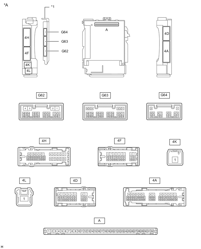
*A Main Body ECU (Multiplex Network Body ECU) with 3 connectors - - *1 Main Body ECU (Multiplex Network Body ECU) - -
-
Remove the main body ECU (multiplex network body ECU).
-
Reconnect the junction block assembly LH connectors.
-
Measure the voltage and resistance according to the value(s) in the table below.
Tester Connection Wiring Color Terminal Description Condition Specified Condition A-31 (BECU) - Body ground None - Body ground Power supply Always 11 to 14 V A-30 (ACC) - Body ground None - Body ground ACC power supply Engine switch off → on (ACC) Below 1 V → 11 to 14 V A-32 (IG) - Body ground None - Body ground IG power supply Engine switch off → on (IG) Below 1 V → 11 to 14 V A-11 (GND1) - Body ground None - Body ground Ground Always Below 1 Ω G62-25 (RLSC) - Body ground BR - Body ground Slide door close switch RH signal Slide door close switch RH on → off Below 1 Ω → 10 kΩ or higher G62-26 (RRSC) - Body ground L - Body ground Slide door close switch LH signal Slide door close switch LH on → off Below 1 Ω → 10 kΩ or higher G63-3 (RRSD) - Body ground SB - Body ground Slide door open switch LH signal Slide door open switch LH on → off Below 1 Ω → 10 kΩ or higher G63-16 (RLSD) - Body ground R - Body ground Slide door open switch RH signal Slide door open switch RH on → off Below 1 Ω → 10 kΩ or higher
-