POWER SLIDE DOOR SYSTEM When Engine is Running or Stopped and Door Control Switch is Pressed, Door does not Open or Close (RH Door)
DESCRIPTION
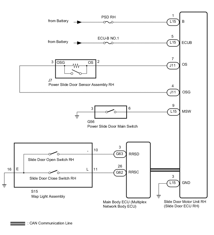
The slide door motor unit RH (slide door ECU RH) receives the slide door open/close switch signals from the main body ECU (multiplex network body ECU) and performs power slide door open and close operations.
WIRING DIAGRAM
CAUTION / NOTICE / HINT
Note
-
If the main body ECU (multiplex network body ECU) is replaced, refer to Service Bulletin.
-
The power slide door system uses the CAN communication system. First perform the inspections in "How to Proceed with Troubleshooting" to confirm that there are no communication malfunctions before proceeding with troubleshooting.
-
Inspect the fuses for circuits related to this system before performing the following inspection procedure.
PROCEDURE
-
CHECK SLIDE DOOR CLOSER SYSTEM
-
Check that the slide door closer operates.
OK Slide door closer operates normally. Result Proceed to OK NG
NG 
GO TO SLIDE DOOR CLOSER SYSTEM Click here
OK 
-
-
CHECK BASIC FUNCTIONS
-
Operation conditions when the engine switch is on (IG):
-
Power slide door main switch on
-
Slide door unlocked (unlock detection switch on)
-
Vehicle speed 3 km/h (2 mph) or less
-
When any of the following conditions is met:
-
Shift lever in P
-
Brake pedal depressed (stop light switch assembly on)
-
Parking brake locked (electric parking brake switch indicator light illuminated)
-
-
-
Operation conditions when the engine switch is off:
-
Power slide door main switch on
-
Slide door unlocked (unlock detection switch on)
Result Result Proceed to Operation conditions met, but does not operate A Motor operation sounds occur, but slide door does not operate (lock is released, but slide door does not open) B -
B
REPLACE SLIDE DOOR MOTOR UNIT RH Click here
A
-
-
CHECK METER / GAUGE SYSTEM
-
Using the GTS, check whether the vehicle speed signal is normal.
Tech Tips
Check that the vehicle speed displayed for "Vehicle Speed Meter" in the Data List is 0 km/h (0 mph) when the vehicle is stationary.
OK Meter / gauge system operates normally. Result Proceed to OK NG
NG
GO TO METER / GAUGE SYSTEM Click here
OK
-
-
CHECK SFI SYSTEM
-
Check whether the SFI system operates normally.
for 2AR-FE:
for 2GR-FE:
OK SFI system operates normally. Result Result Proceed to OK A NG (for 2AR-FE) B NG (for 2GR-FE) C
B
GO TO SFI SYSTEM Click here
C
GO TO SFI SYSTEM Click here
A
-
-
CHECK VEHICLE STABILITY CONTROL SYSTEM
-
Check whether the vehicle stability control system operates normally.
OK Vehicle stability control system operates normally. Result Proceed to OK NG
NG
GO TO VEHICLE STABILITY CONTROL SYSTEM Click here
OK
-
-
CHECK ELECTRIC PARKING BRAKE SYSTEM
-
Check whether the electric parking brake system operates normally.
OK Electric parking brake system operates normally. Result Proceed to OK NG
NG
GO TO ELECTRIC PARKING BRAKE SYSTEM Click here
OK
-
-
CHECK LIGHTING SYSTEM
-
Check whether the lighting system operates normally.
OK Lighting system operates normally. Result Proceed to OK NG
NG
GO TO LIGHTING SYSTEM Click here
OK
-
-
CHECK HARNESS AND CONNECTOR (SLIDE DOOR MOTOR UNIT RH - BATTERY AND BODY GROUND)
-
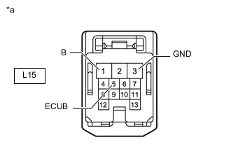
*a Front view of wire harness connector
(to Slide Door Motor Unit RH [Slide Door ECU RH])
Disconnect the slide door motor unit RH (slide door ECU RH) connector.
-
Measure the voltage according to the value(s) in the table below.
Standard Voltage Tester Connection Condition Specified Condition L15-1 (B) - Body ground Always 11 to 14 V L15-5 (ECUB) - Body ground Always 11 to 14 V -
Measure the resistance according to the value(s) in the table below.
Standard Resistance Tester Connection Condition Specified Condition L15-3 (GND) - Body ground Always Below 1 Ω Result Proceed to OK NG
NG
REPAIR OR REPLACE HARNESS OR CONNECTOR
OK
-
-
READ VALUE USING GTS
-
Read the Data List according to the display on the GTS.
Body Electrical > Rear Right Door > Data ListTester Display Measurement Item Normal Condition Reference Value Diagnostic Note PSD Main Switch Power slide door main switch signal ON or OFF ON: Power slide door main switch on
OFF: Power slide door main switch off
-
Body Electrical > Rear Right Door > Data ListTester Display PSD Main Switch OK On the GTS screen, ON or OFF is displayed accordingly. Result Proceed to OK NG
NG 
INSPECT POWER SLIDE DOOR MAIN SWITCH Click here
OK
-
-
READ VALUE USING GTS
-
Read the Data List according to the display on the GTS.
Body Electrical > Main Body > Data ListTester Display Measurement Item Normal Condition Reference Value Diagnostic Note Slide Door RH Close Switch Slide door close switch RH signal ON or OFF ON: Slide door close switch RH on
OFF: Slide door close switch RH off
- Slide Door RH Open Switch Slide door open switch RH signal ON or OFF ON: Slide door open switch RH on
OFF: Slide door open switch RH off
-
Body Electrical > Main Body > Data ListTester Display Slide Door RH Close Switch Slide Door RH Open Switch OK On the GTS screen, ON or OFF is displayed accordingly. Result Proceed to OK NG
NG
INSPECT MAP LIGHT ASSEMBLY Click here
OK
-
-
READ VALUE USING GTS
-
Read the Data List according to the display on the GTS.
Body Electrical > Rear Right Door > Data ListTester Display Measurement Item Normal Condition Reference Value Diagnostic Note PSD Touch Sensor Power slide door sensor assembly RH signal OFF, ON or Open OFF: Power slide door sensor assembly RH not pressed
ON: Power slide door sensor assembly RH pressed
Open: Power slide door sensor assembly RH open
-
Body Electrical > Rear Right Door > Data ListTester Display PSD Touch Sensor OK On the GTS screen, ON or OFF is displayed accordingly. Result Proceed to OK NG
OK
REPLACE SLIDE DOOR MOTOR UNIT RH Click here
NG
INSPECT POWER SLIDE DOOR SENSOR ASSEMBLY RH Click here
-
-
INSPECT POWER SLIDE DOOR MAIN SWITCH
-
Remove the power slide door main switch.
-
Inspect the power slide door main switch.
Result Proceed to OK NG
NG
REPLACE POWER SLIDE DOOR MAIN SWITCH Click here
OK
-
-
CHECK HARNESS AND CONNECTOR (POWER SLIDE DOOR MAIN SWITCH - SLIDE DOOR MOTOR UNIT RH AND BODY GROUND)
-
Disconnect the G56 power slide door main switch connector.
-
Disconnect the L15 slide door motor unit RH (slide door ECU RH) connector.
-
Measure the resistance according to the value(s) in the table below.
Standard Resistance Tester Connection Condition Specified Condition G56-6 - L15-9 (MSW) Always Below 1 Ω G56-3 - Body ground Always Below 1 Ω G56-6 or L15-9 (MSW) - Body ground Always 10 kΩ or higher Result Proceed to OK NG
OK
REPLACE SLIDE DOOR MOTOR UNIT RH Click here
NG
REPAIR OR REPLACE HARNESS OR CONNECTOR
-
-
INSPECT MAP LIGHT ASSEMBLY
-
Remove the map light assembly.
-
Inspect the map light assembly.
Result Proceed to OK NG
NG
REPLACE MAP LIGHT ASSEMBLY Click here
OK
-
-
CHECK HARNESS AND CONNECTOR (MAP LIGHT ASSEMBLY - MAIN BODY ECU AND BODY GROUND)
-
Disconnect the S15 map light assembly connector.
-
Disconnect the G62 and G63 main body ECU (multiplex network body ECU) connectors.
-
Measure the resistance according to the value(s) in the table below.
Standard Resistance Tester Connection Condition Specified Condition S15-10 (-) - G63-3 (RRSD) Always Below 1 Ω S15-11 (L) - G62-26 (RRSC) Always Below 1 Ω S15-16 (E) - Body ground Always Below 1 Ω S15-10 (-) or G63-3 (RRSD) - Body ground Always 10 kΩ or higher S15-11 (L) or G62-26 (RRSC) - Body ground Always 10 kΩ or higher Result Proceed to OK NG
OK
REPLACE MAIN BODY ECU (MULTIPLEX NETWORK BODY ECU) Click here
NG
REPAIR OR REPLACE HARNESS OR CONNECTOR
-
-
INSPECT POWER SLIDE DOOR SENSOR ASSEMBLY RH
-
Remove the power slide door sensor assembly RH.
-
Inspect the power slide door sensor assembly RH.
Result Proceed to OK NG
NG
REPLACE POWER SLIDE DOOR SENSOR ASSEMBLY RH Click here
OK
-
-
CHECK HARNESS AND CONNECTOR (SLIDE DOOR MOTOR UNIT RH - POWER SLIDE DOOR SENSOR ASSEMBLY RH)
-
Disconnect the J11 slide door motor unit RH (slide door ECU RH) connector.
-
Disconnect the J7 power slide door sensor assembly RH connector.
-
Measure the resistance according to the value(s) in the table below.
Standard Resistance Tester Connection Condition Specified Condition J11-7 (OS) - J7-2 (OS) Always Below 1 Ω J11-4 (OSG) - J7-3 (OSG) Always Below 1 Ω J11-7 (OS) or J7-2 (OS) - Body ground Always 10 kΩ or higher J11-4 (OSG) or J7-3 (OSG) - Body ground Always 10 kΩ or higher Result Proceed to OK NG
OK
REPLACE SLIDE DOOR MOTOR UNIT RH Click here
NG
REPAIR OR REPLACE HARNESS OR CONNECTOR
-