TILT ROOF HOUSING INSTALLATION
PROCEDURE
-
INSTALL TILT ROOF WEATHERSTRIP
-
Install the tilt roof weatherstrip as follows:
-
Position the joint of the tilt roof weatherstrip at the rear center.
-
Align the marks on the tilt roof weatherstrip with the middle marks at the corners of the tilt roof panel and install the tilt roof weatherstrip.
Tech Tips
Make sure that the tilt roof weatherstrip markings are aligned within the range as shown in the illustration.
-
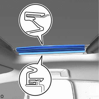
Install the lip of the tilt roof weatherstrip firmly.
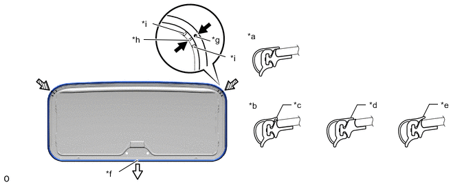
*a Normal *b Abnormal *c Pinched *d Exposed *e Gap (raised, wavy, etc.) *f Center of Joint *g Tilt Roof Weatherstrip Mark *h Middle Mark *i Side Mark - - 
Vehicle Rear 
Alignment Mark
-
-
-
INSTALL TILT ROOF GLASS SEAL
-
Clean the attachment surface.
-
When reusing the tilt roof glass sub-assembly, remove any remaining double-sided tape on the tilt roof glass sub-assembly.
-
Using a non-residue solvent, clean the attachment surface.
-
-
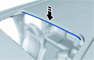
Peel off the backing paper of a new tilt roof glass seal.
-

Install in this Direction Install the tilt roof glass seal to the tilt roof glass sub-assembly.
-
-
INSTALL TILT ROOF LOCK HANDLE ASSEMBLY
-
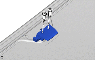
Install the tilt roof lock handle assembly with the 2 screws.
- Torque:
- 4.0 N*m { 41 kgf*cm, 35 in.*lbf }
-
-
INSTALL TILT ROOF PANEL COVER
-
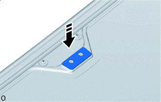
Install in this Direction Install the tilt roof panel cover.
-
-
INSTALL TILT ROOF LOCK STRIKER
-
Install the tilt roof lock striker with the 3 bolts.
- Torque:
- 5.4 N*m { 55 kgf*cm, 48 in.*lbf }
-
-
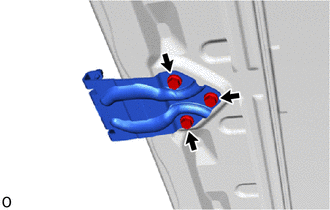
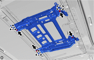
INSTALL TILT ROOF HOUSING SUB-ASSEMBLY
-
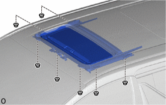
Install the tilt roof housing sub-assembly with the 7 nuts.
- Torque:
- 7.4 N*m { 75 kgf*cm, 65 in.*lbf }
-
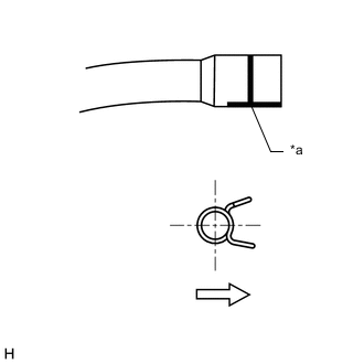
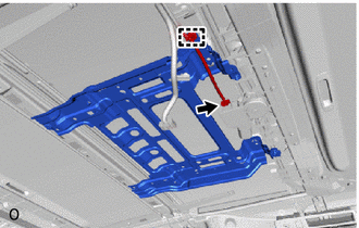
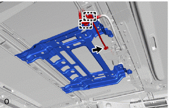
*a Marking Vehicle Inside Connect the 2 tilt roof drain hose assemblies so that each mark faces downward.
Note
Make sure that the clamping area of the clip is facing toward the inside of the vehicle and comes above the marking.
-
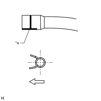
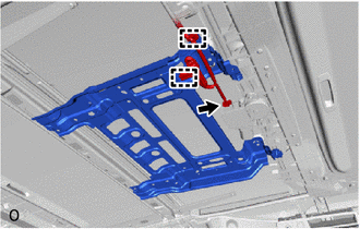
*a Marking Vehicle Inside Connect the 2 sliding roof drain hoses so that each mark faces downward.
Note
Make sure that the clamping area of the clip is facing toward the inside of the vehicle and comes above the marking.
-
-
INSTALL TILT ROOF GLASS SUB-ASSEMBLY
-
Using a T25 "TORX" socket wrench, temporarily install the tilt roof glass sub-assembly with the 4 screws.
-
Perform a level check.
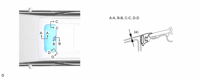
-
Check the difference in level for "a" between the roof panel and the upper surface of the tilt roof weatherstrip when the tilt roof glass is fully closed.
Standard Area Measurement A - A 0 + 1.5 mm (0 + 0.0591 in.)
0 - 1.5 mm (0 - 0.0591 in.)
B - B 0 + 1.5 mm (0 + 0.0591 in.)
0 - 1.5 mm (0 - 0.0591 in.)
C - C 0 + 1.5 mm (0 + 0.0591 in.)
0 - 1.5 mm (0 - 0.0591 in.)
D - D 0 + 1.5 mm (0 + 0.0591 in.)
0 - 1.0 mm (0 - 0.0394 in.)
Tech Tips
"+" represents the condition that the glass is above the panel level. "-" represents the condition that the glass is below the panel level.
-
-
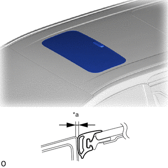
*a Even Perform a gap check.
-
Check the gap between the roof panel and roof glass.
Note
The gap must be even all around.
-
-
After adjusting the tilt roof glass sub-assembly, using a T25 "TORX" socket wrench, install the tilt roof glass sub-assembly with the 4 screws.
- Torque:
- 4.0 N*m { 41 kgf*cm, 35 in.*lbf }
-
-
CHECK FOR WATER LEAK
-
After adjusting the tilt roof glass sub-assembly, check for water leakage into the vehicle interior.
-
If there are any leaks, readjust the tilt roof glass sub-assembly.
-
-
INSTALL TELEVISION BRACKET
-
Attach the guide and clip and install the television bracket.
-
Install the 4 bolts.
-
w/ 9 Inch Television Display:
-
Attach the clamp.
-
Connect the sliding roof drive gear connector.
-
-
w/ 12 Inch Television Display:
-
Attach the clamp.
-
Connect the sliding roof drive gear connector.
-
-
w/o Television Display:
-
Attach the clamp.
-
Connect the sliding roof drive gear connector.
-
-
-
INSTALL ROOF HEADLINING ASSEMBLY
-
INSTALL FRONT SLIDING ROOF GARNISH RH
-
Fully open the sunshade trim sub-assembly.
-
Install the front sliding roof garnish RH as shown in the illustration.
-
-
INSTALL FRONT SLIDING ROOF GARNISH LH
Tech Tips
Use the same procedure described for the RH side.
-
CONNECT CABLE TO NEGATIVE BATTERY TERMINAL
Note
When disconnecting the cable, some systems need to be initialized after the cable is reconnected.
-
RESET SLIDING ROOF DRIVE GEAR ASSEMBLY
-
CHECK SLIDING ROOF SYSTEM