SLIDING ROOF SYSTEM TERMINALS OF ECU
-
CHECK SLIDING ROOF ECU (SLIDING ROOF DRIVE GEAR ASSEMBLY)
-
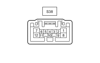
Disconnect the S38 sliding roof ECU (sliding roof drive gear assembly) connector.
-
Measure the resistance and voltage according to the value(s) in the table below.
Tester Connection Wiring Color Terminal Description Condition Specified Condition S38-1 (IG) - Body ground L - Body ground IG power supply Engine switch off Below 1 V Engine switch on (IG) 11 to 14 V S38-8 (B) - Body ground SB - Body ground Battery power supply Always 11 to 14 V S38-12 (E) - Body ground W-B - Body ground Ground Always Below 1 Ω -
Reconnect the S38 sliding roof ECU (sliding roof drive gear assembly) connector.
-
Measure the voltage according to the value(s) in the table below.
Tester Connection Wiring Color Terminal Description Condition Specified Condition S38-5 (CLS) - Body ground GR - Body ground Slide roof switch (CLOSE) signal Slide roof switch (CLOSE) off → on 11 to 14 V → Below 1 V S38-7 (OPN) - Body ground BR - Body ground Slide roof switch (OPEN) signal Slide roof switch (OPEN) off → on 11 to 14 V → Below 1 V -
Measure the waveform according to the value(s) in the table below.
Tester Connection Wiring Color Terminal Description Condition Specified Condition S38-11 (MPX1) - Body ground LG - Body ground LIN communication line Engine switch on (IG) Pulse generation
-
-
CHECK MAIN BODY ECU (MULTIPLEX NETWORK BODY ECU)