POWER SLIDE DOOR SYSTEM, Diagnostic DTC:B2255
| DTC Code | DTC Name |
|---|---|
| B2255 | Door Closer Switch Failure on Rear Left Door |
DESCRIPTION
This DTC is output when the half-latch switch and full-latch switch in the rear slide door lock assembly LH input a malfunction signal.
| DTC No. | Detection Item | DTC Detection Condition | Trouble Area |
|---|---|---|---|
| B2255 | Door Closer Switch Failure on Rear Left Door | Slide door motor unit LH (slide door ECU LH) detects half-latch switch and full-latch switch malfunction signal input in rear slide door lock assembly LH |
|
WIRING DIAGRAM
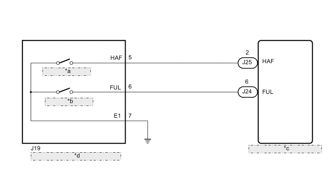
| *a | Half-latch Switch |
| *b | Full-latch Switch |
| *c | Slide Door Motor Unit LH (Slide Door ECU LH) |
| *d | Rear Slide Door Lock Assembly LH |
PROCEDURE
-
CHECK FOR DTC
-
Clear the DTC.
Body Electrical > Rear Left Door > Clear DTCs -
Check for DTC.
Body Electrical > Rear Left Door > Trouble CodesOK DTC B2255 is not output Result Proceed to OK NG
OK 
USE SIMULATION METHOD TO CHECK Click here
NG 
-
-
READ VALUE USING GTS
-
Read the Data List according to the display on the GTS.
Body Electrical > Rear Left Door > Data ListTester Display Measurement Item Normal Condition Reference Value Diagnostic Note Half Switch Status of the half-latch switch ON or OFF ON: Half-latch switch on
OFF: Half-latch switch off
Check timing chart* Full Switch Status of the full-latch switch ON or OFF ON: Full-latch switch on
OFF: Full-latch switch off
Check timing chart*
-
*: Timing chart
Body Electrical > Rear Left Door > Data ListTester Display Half Switch Full Switch OK On the GTS screen, ON or OFF is displayed accordingly. Result Proceed to OK NG -
OK
REPLACE SLIDE DOOR MOTOR UNIT LH Click here
NG
-
-
INSPECT REAR SLIDE DOOR LOCK ASSEMBLY LH
-
Remove the rear slide door lock assembly LH.
-
Inspect the rear slide door lock assembly LH.
Result Proceed to OK NG
NG
REPLACE REAR SLIDE DOOR LOCK ASSEMBLY LH Click here
OK
-
-
CHECK HARNESS AND CONNECTOR (REAR SLIDE DOOR LOCK ASSEMBLY LH - SLIDE DOOR MOTOR UNIT LH AND BODY GROUND)
-
Disconnect the J19 rear slide door lock assembly LH connector.
-
Disconnect the J24 and J25 slide door motor unit LH (slide door ECU LH) connectors.
-
Measure the resistance according to the value(s) in the table below.
Standard Resistance Tester Connection Condition Specified Condition J19-6 (FUL) - J24-6 (FUL) Always Below 1 Ω J19-5 (HAF) - J25-2 (HAF) Always Below 1 Ω J19-7 (E1) - Body ground Always Below 1 Ω J19-6 (FUL) or J24-6 (FUL) - Body ground Always 10 kΩ or higher J19-5 (HAF) or J25-2 (HAF) - Body ground Always 10 kΩ or higher Result Proceed to OK NG
OK
REPLACE SLIDE DOOR MOTOR UNIT LH Click here
NG
REPAIR OR REPLACE HARNESS OR CONNECTOR
-