POWER SLIDE DOOR SYSTEM, Diagnostic DTC:B2260
| DTC Code | DTC Name |
|---|---|
| B2260 | Power Slide Door Neutral Closer Switch RH Malfunction during Open Operation |
DESCRIPTION
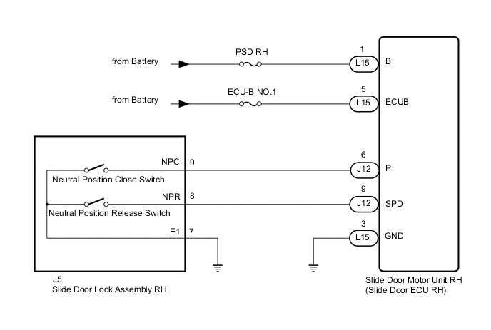
This DTC is output when the neutral position switch (close/release) in the slide door lock assembly RH inputs a malfunction signal during a slide door open operation.
| DTC No. | Detection Item | DTC Detection Condition | Trouble Area |
|---|---|---|---|
| B2260 | Power Slide Door Neutral Closer Switch RH Malfunction during Open Operation | Slide door motor unit RH (slide door ECU RH) detects neutral position switch (close/release) malfunction signal in slide door lock assembly RH during slide door open operation |
|
WIRING DIAGRAM
CAUTION / NOTICE / HINT
Note
Inspect the fuses for circuits related to this system before performing the following inspection procedure.
PROCEDURE
-
CHECK FOR DTC
-
Clear the DTC.
Body Electrical > Rear Right Door > Clear DTCs -
Check for DTC.
Body Electrical > Rear Right Door > Trouble CodesOK DTC B2260 is not output Result Proceed to OK NG
OK 
USE SIMULATION METHOD TO CHECK Click here
NG 
-
-
CHECK HARNESS AND CONNECTOR (SLIDE DOOR MOTOR UNIT RH - BATTERY AND BODY GROUND)
-
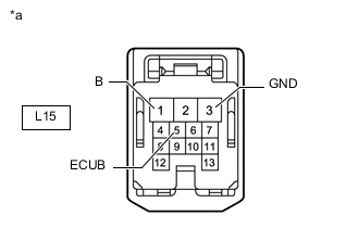
*a Front view of wire harness connector
(to Slide Door Motor Unit RH [Slide Door ECU RH])
Disconnect the slide door motor unit RH (slide door ECU RH) connector.
-
Measure the voltage according to the value(s) in the table below.
Standard Voltage Tester Connection Condition Specified Condition L15-1 (B) - Body ground Always 11 to 14 V L15-5 (ECUB) - Body ground Always 11 to 14 V -
Measure the resistance according to the value(s) in the table below.
Standard Resistance Tester Connection Condition Specified Condition L15-3 (GND) - Body ground Always Below 1 Ω Result Proceed to OK NG
NG
REPAIR OR REPLACE HARNESS OR CONNECTOR
OK
-
-
READ VALUE USING GTS
-
Read the Data List according to the display on the GTS.
Body Electrical > Rear Right Door > Data ListTester Display Measurement Item Normal Condition Reference Value Diagnostic Note Neutral Position Close Switch Status of the neutral position close switch ON or OFF ON: Neutral position close switch on
OFF: Neutral position close switch off
Check timing chart* Neutral Position Release Switch Status of the neutral position release switch ON or OFF ON: Neutral position release switch on
OFF: Neutral position release switch off
Check timing chart*
-
*: Timing chart
Body Electrical > Rear Right Door > Data ListTester Display Neutral Position Close Switch Neutral Position Release Switch OK On the GTS screen, ON or OFF is displayed accordingly. Result Proceed to OK NG -
OK
REPLACE SLIDE DOOR MOTOR UNIT RH Click here
NG
-
-
INSPECT SLIDE DOOR LOCK ASSEMBLY RH
-
Remove the slide door lock assembly RH.
-
Inspect the slide door lock assembly RH.
Result Proceed to OK NG
NG
REPLACE SLIDE DOOR LOCK ASSEMBLY RH Click here
OK
-
-
CHECK HARNESS AND CONNECTOR (SLIDE DOOR LOCK ASSEMBLY RH - SLIDE DOOR MOTOR UNIT RH AND BODY GROUND)
-
Disconnect the J5 slide door lock assembly RH connector.
-
Disconnect the J12 slide door motor unit RH (slide door ECU RH) connector.
-
Measure the resistance according to the value(s) in the table below.
Standard Resistance Tester Connection Condition Specified Condition J5-9 (NPC) - J12-6 (P) Always Below 1 Ω J5-8 (NPR) - J12-9 (SPD) Always Below 1 Ω J5-7 (E1) - Body ground Always Below 1 Ω J5-9 (NPC) or J12-6 (P) - Body ground Always 10 kΩ or higher J5-8 (NPR) or J12-9 (SPD) - Body ground Always 10 kΩ or higher Result Proceed to OK NG
OK
REPLACE SLIDE DOOR MOTOR UNIT RH Click here
NG
REPAIR OR REPLACE HARNESS OR CONNECTOR
-