POWER SLIDE DOOR SYSTEM, Diagnostic DTC:B2224
| DTC Code | DTC Name |
|---|---|
| B2224 | Power Slide Door Pulse Sensor Malfunction on Rear Left Door |
DESCRIPTION
This DTC is output when there is a malfunction in the door pulse sensor system inside the slide door motor unit LH (slide door ECU LH) and a normal waveform is not input to the door pulse sensor during a power slide door operation.
| DTC No. | Detection Item | DTC Detection Condition | Trouble Area |
|---|---|---|---|
| B2224 | Power Slide Door Pulse Sensor Malfunction on Rear Left Door | Door sensor malfunction in slide door motor unit LH (slide door ECU LH) |
|
WIRING DIAGRAM
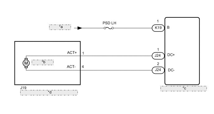
| *a | from Battery |
| *b | Closer Motor |
| *c | Slide Door Motor Unit LH (Slide Door ECU LH) |
| *d | Rear Slide Door Lock Assembly LH |
CAUTION / NOTICE / HINT
Note
Inspect the fuses for circuits related to this system before performing the following inspection procedure.
PROCEDURE
-
CHECK FOR DTC
-
Clear the DTC.
Body Electrical > Rear Left Door > Clear DTCs -
Check for DTC.
Body Electrical > Rear Left Door > Trouble CodesOK DTC B2224 is not output Result Proceed to OK NG
OK 
USE SIMULATION METHOD TO CHECK Click here
NG 
-
-
CHECK HARNESS AND CONNECTOR (SLIDE DOOR MOTOR UNIT LH - BATTERY)
-
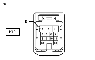
*a Front view of wire harness connector
(to Slide Door Motor Unit LH [Slide Door ECU LH])
Disconnect the slide door motor unit LH (slide door ECU LH) connector.
-
Measure the voltage according to the value(s) in the table below.
Standard Voltage Tester Connection Condition Specified Condition K19-1 (B) - Body ground Always 11 to 14 V Result Proceed to OK NG
NG
REPAIR OR REPLACE HARNESS OR CONNECTOR
OK
-
-
PERFORM ACTIVE TEST USING GTS
-
Perform the Active Test according to the display on the GTS.
Body Electrical > Rear Left Door > Active TestTester Display Measurement Item Control Range Diagnostic Note PSD Open Slide door open ON or OFF -
Body Electrical > Rear Left Door > Active TestTester Display PSD Open OK Rear slide door lock assembly LH (closer motor) operates. Result Proceed to OK NG
OK
REPLACE SLIDE DOOR MOTOR UNIT LH Click here
NG
-
-
INSPECT REAR SLIDE DOOR LOCK ASSEMBLY LH
-
Remove the rear slide door lock assembly LH.
-
Inspect the rear slide door lock assembly LH.
Result Proceed to OK NG
NG
REPLACE REAR SLIDE DOOR LOCK ASSEMBLY LH Click here
OK
-
-
CHECK HARNESS AND CONNECTOR (REAR SLIDE DOOR LOCK ASSEMBLY LH - SLIDE DOOR MOTOR UNIT LH)
-
Disconnect the J19 rear slide door lock assembly LH connector.
-
Disconnect the J24 slide door motor unit LH (slide door ECU LH) connector.
-
Measure the resistance according to the value(s) in the table below.
Standard Resistance Tester Connection Condition Specified Condition J19-1 (ACT+) - J24-1 (DC+) Always Below 1 Ω J19-4 (ACT-) - J24-2 (DC-) Always Below 1 Ω J19-1 (ACT+) or J24-1 (DC+) - Body ground Always 10 kΩ or higher J19-4 (ACT-) or J24-2 (DC-) - Body ground Always 10 kΩ or higher Result Proceed to OK NG
OK
REPLACE SLIDE DOOR MOTOR UNIT LH Click here
NG
REPAIR OR REPLACE HARNESS OR CONNECTOR
-