WINDSHIELD DEICER SYSTEM Windshield Deicer does not Operate
DESCRIPTION
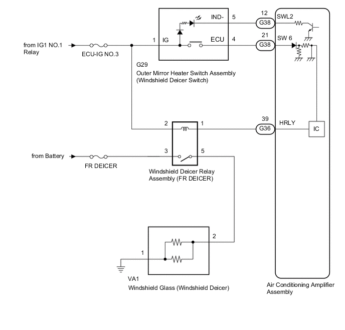
When the outer mirror heater switch assembly (windshield deicer switch) is operated, the operation signal is transmitted to the air conditioning amplifier assembly. When the air conditioning amplifier assembly receives the signal, it turns on the windshield deicer relay assembly (FR DEICER) to operate the windshield deicer system.
WIRING DIAGRAM
CAUTION / NOTICE / HINT
Note
-
Inspect the fuses for circuits related to this system before performing the following procedure.
-
If the battery voltage becomes low, windshield deicer operation is canceled to prioritize supplying power to the power steering system.
PROCEDURE
-
PERFORM ACTIVE TEST USING GTS
-
Using the GTS, perform the Active Test.
Body Electrical > Air Conditioner > Active TestTester Display Measurement Item Control Range Diagnostic Note Deicer Relay (Front) Windshield glass (windshield deicer) OFF or ON -
Body Electrical > Air Conditioner > Active TestTester Display Deicer Relay (Front) OK The windshield deicer system operates normally. Result Proceed to OK NG
NG 
CHECK HARNESS AND CONNECTOR (WINDSHIELD GLASS [WINDSHIELD DEICER] - BATTERY) Click here
OK 
-
-
INSPECT OUTER MIRROR HEATER SWITCH ASSEMBLY (WINDSHIELD DEICER SWITCH)
-
Remove the outer mirror heater switch assembly (windshield deicer switch)
-
Inspect the outer mirror heater switch assembly (windshield deicer switch)
Result Proceed to OK NG
NG 
REPLACE OUTER MIRROR HEATER SWITCH ASSEMBLY (WINDSHIELD DEICER SWITCH) Click here
OK
-
-
CHECK HARNESS AND CONNECTOR (OUTER MIRROR HEATER SWITCH ASSEMBLY [WINDSHIELD DEICER SWITCH] - BATTERY)
-
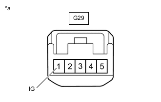
*a Front view of wire harness connector
(to Outer Mirror Heater Switch Assembly [Windshield Deicer Switch])
Disconnect the outer mirror heater switch assembly (windshield deicer switch) connector.
-
Measure the voltage according to the value(s) in the table below.
Standard Voltage Tester Connection Switch Condition Specified Condition G29-1 (IG) - Body ground Engine switch on (IG) 11 to 14 V Engine switch off Below 1 V Result Proceed to OK NG
NG
REPAIR OR REPLACE HARNESS OR CONNECTOR
OK
-
-
CHECK HARNESS AND CONNECTOR (AIR CONDITIONING AMPLIFIER ASSEMBLY - OUTER MIRROR HEATER SWITCH ASSEMBLY [WINDSHIELD DEICER SWITCH])
-
Disconnect the G38 air conditioning amplifier assembly connector.
-
Disconnect the G29 outer mirror heater switch assembly (windshield deicer switch) connector.
-
Measure the resistance according to the value(s) in the table below.
Standard Resistance Tester Connection Condition Specified Condition G38-21 (SW 6) - G29-4 (ECU) Always Below 1 Ω G38-12 (SWL2) - G29-5 (IND-) Always Below 1 Ω G38-21 (SW 6) or G29-4 (ECU) - Body ground Always 10 kΩ or higher G38-12 (SWL2) or G29-5 (IND-) - Body ground Always 10 kΩ or higher Result Proceed to OK NG
OK
REPLACE AIR CONDITIONING AMPLIFIER ASSEMBLY for LHD: REPLACE AIR CONDITIONING AMPLIFIER ASSEMBLY Click here
REPLACE AIR CONDITIONING AMPLIFIER ASSEMBLY for RHD: REPLACE AIR CONDITIONING AMPLIFIER ASSEMBLY Click hereNG
REPAIR OR REPLACE HARNESS OR CONNECTOR
-
-
CHECK HARNESS AND CONNECTOR (WINDSHIELD GLASS [WINDSHIELD DEICER] - BATTERY)
-
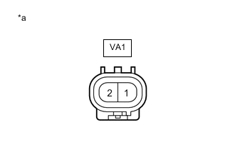
*a Front view of wire harness connector
(to Windshield Glass [Windshield Deicer])
Disconnect the windshield glass (windshield deicer) connector.
-
Measure the voltage according to the value(s) in the table below.
Standard Voltage Tester Connection Switch Condition Specified Condition VA1-2 - Body ground Engine switch on (IG), outer mirror heater switch assembly (windshield deicer switch) on 11 to 14 V Result Proceed to OK NG
NG
INSPECT WINDSHIELD DEICER RELAY ASSEMBLY (FR DEICER) Click here
OK
-
-
CHECK HARNESS AND CONNECTOR (WINDSHIELD GLASS [WINDSHIELD DEICER] - BODY GROUND)
-
*a Front view of wire harness connector
(to Windshield Glass [Windshield Deicer])
Disconnect the windshield glass (windshield deicer) connector.
-
Measure the resistance according to the value(s) in the table below.
Standard Resistance Tester Connection Condition Specified Condition VA1-1 - Body ground Always Below 1 Ω Result Proceed to OK NG
OK
REPLACE WINDSHIELD GLASS (WINDSHIELD DEICER) Click here
NG
REPAIR OR REPLACE HARNESS OR CONNECTOR
-
-
INSPECT WINDSHIELD DEICER RELAY ASSEMBLY (FR DEICER)
-
Remove the windshield deicer relay assembly (FR DEICER) from the No. 2 engine room relay block.
-
Inspect the windshield deicer relay assembly (FR DEICER).
Result Proceed to OK NG
NG
REPLACE WINDSHIELD DEICER RELAY ASSEMBLY (FR DEICER)
OK
-
-
CHECK HARNESS AND CONNECTOR (WINDSHIELD DEICER RELAY ASSEMBLY [FR DEICER] - BATTERY)
-
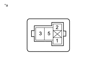
*a Front view of wire harness connector
(to Windshield Deicer Relay Assembly [FR DEICER])
Remove the windshield deicer relay assembly (FR DEICER) from the No. 2 engine room relay block.
-
Measure the voltage according to the value(s) in the table below.
Standard Voltage Tester Connection Condition Specified Condition Windshield deicer relay assembly (FR DEICER) terminal 3 - Body ground Always 11 to 14 V Windshield deicer relay assembly (FR DEICER) terminal 2 - Body ground Engine switch on (IG) 11 to 14 V Result Proceed to OK NG
NG
REPAIR OR REPLACE HARNESS OR CONNECTOR
OK
-
-
CHECK HARNESS AND CONNECTOR (WINDSHIELD DEICER RELAY ASSEMBLY [FR DEICER] - AIR CONDITIONING AMPLIFIER ASSEMBLY AND WINDSHIELD GLASS [WINDSHIELD DEICER])
-
Remove the windshield deicer relay assembly (FR DEICER) from the No. 2 engine room relay block.
-
Disconnect the G36 air conditioning amplifier assembly connector.
-
Disconnect the VA1 windshield glass (windshield deicer) connector.
-
Measure the resistance according to the value(s) in the table below.
Standard Resistance Tester Connection Condition Specified Condition Windshield deicer relay assembly (FR DEICER) terminal 1 - G36-39 (HRLY) Always Below 1 Ω Windshield deicer relay assembly (FR DEICER) terminal 5 - VA1-2 Always Below 1 Ω Windshield deicer relay assembly (FR DEICER) terminal 1 or G36-39 (HRLY) - Body ground Always 10 kΩ or higher Windshield deicer relay assembly (FR DEICER) terminal 5 or VA1-2 - Body ground Always 10 kΩ or higher Result Proceed to OK NG
OK
REPLACE AIR CONDITIONING AMPLIFIER ASSEMBLY for LHD: REPLACE AIR CONDITIONING AMPLIFIER ASSEMBLY Click here
REPLACE AIR CONDITIONING AMPLIFIER ASSEMBLY for RHD: REPLACE AIR CONDITIONING AMPLIFIER ASSEMBLY Click hereNG
REPAIR OR REPLACE HARNESS OR CONNECTOR
-