WINDSHIELD GLASS REMOVAL
CAUTION / NOTICE / HINT
The necessary procedures (adjustment, calibration, initialization or registration) that must be performed after parts are removed, installed or replaced during the windshield glass removal/installation are shown below.
| Replacement Part or Procedure | Necessary Procedures | Effects / Inoperative when not Performed | Link |
|---|---|---|---|
| Disconnect cable from negative battery terminal | Drive the vehicle until stop and start control is permitted (approximately 15 to 40 minutes) | Stop and start system | |
| Memorize steering angle neutral point | Panoramic view monitor system | ||
| Initialize back door lock | Power door lock control system | ||
| Initialize servo motor | Air conditioning system | ||
| Reset slide door close position | Power slide door system | ||
| Reset back door close position | Power back door system |
Tech Tips
-
Use the same procedure for RHD and LHD vehicles.
-
The procedure listed below is for LHD vehicles.
PROCEDURE
-
PRECAUTION
Note
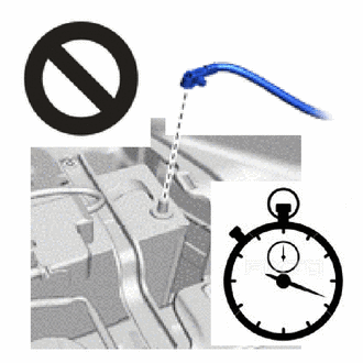
After turning the engine switch off, waiting time may be required before disconnecting the cable from the negative (-) battery terminal. Therefore, make sure to read the disconnecting the cable from the negative (-) battery terminal notice before proceeding with work.
-
DISCONNECT CABLE FROM NEGATIVE BATTERY TERMINAL
CAUTION:
-
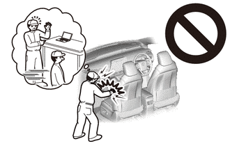
Wait at least 90 seconds after disconnecting the cable from the negative (-) battery terminal to disable the SRS system.
-
If the airbag deploys for any reason, it may cause a serious accident.
Note
When disconnecting the cable, some systems need to be initialized after the cable is reconnected.
-
-
REMOVE WINDSHIELD WIPER ARM COVER
-
REMOVE FRONT WIPER ARM AND BLADE ASSEMBLY LH
-
REMOVE FRONT WIPER ARM AND BLADE ASSEMBLY RH
-
REMOVE COWL WATER EXTRACT SHIELD LH
-
REMOVE COWL WATER EXTRACT SHIELD RH
Tech Tips
Use the same procedure for the LH side.
-
REMOVE COWL TOP VENTILATOR LOUVER SUB-ASSEMBLY
-
REMOVE CENTER ROOF DRIP SIDE FINISH MOULDING LH
-
REMOVE CENTER ROOF DRIP SIDE FINISH MOULDING RH
Tech Tips
Use the same procedure described for the LH side.
-
REMOVE ROOF DRIP SIDE FINISH MOULDING LH
-
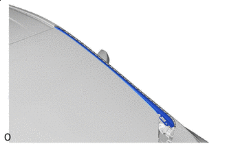

Protective Tape Put protective tape around the roof drip side finish moulding LH.
-
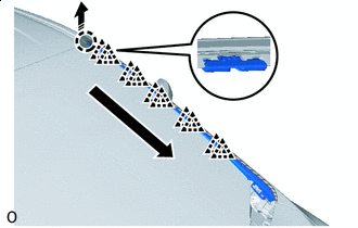

Place Hands Here 
Remove in this Direction 
Remove in this Order Place your hand at the position shown in the illustration and pull in the direction indicated by the arrow to detach the claw of the No. 1 windshield outside moulding clip.
-
Detach the claw of the No. 1 windshield outside moulding clip in the direction and order indicated by the arrow shown in the illustration.
-
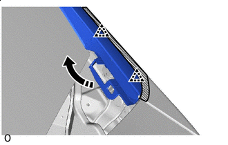
Remove in this Direction Pull up the roof drip side finish moulding LH in the direction indicated by the arrow shown in the illustration to detach the claw and remove the roof drip side finish moulding LH.
-
-
REMOVE ROOF DRIP SIDE FINISH MOULDING RH
Tech Tips
Use the same procedure described for the LH side.
-
REMOVE NO. 1 ROOF DRIP SIDE FINISH MOULDING CLIP
Tech Tips
Perform the following procedure if replacing the No. 1 roof drip side finish moulding clip.
-
Remove the 5 No. 1 roof drip side finish moulding clips.
-
-
REMOVE ASSIST GRIP PLUG
-
REMOVE PILLAR ASSIST GRIP ASSEMBLY
-
REMOVE FRONT PILLAR GARNISH LH
-
REMOVE FRONT PILLAR GARNISH RH
-
REMOVE LOWER FRONT PILLAR GARNISH LH
-
REMOVE LOWER FRONT PILLAR GARNISH RH
-
REMOVE COWL SIDE TRIM BOARD LH
-
REMOVE COWL SIDE TRIM BOARD RH
-
REMOVE DOOR SCUFF PLATE ASSEMBLY LH
-
REMOVE DOOR SCUFF PLATE ASSEMBLY RH
-
REMOVE ASSIST GRIP SUB-ASSEMBLY
-
REMOVE MAP LIGHT ASSEMBLY
-
for LED Type:
-
for Bulb Type:
-
-
REMOVE VISOR BRACKET COVER LH
-
REMOVE VISOR BRACKET COVER RH
-
REMOVE VISOR ASSEMBLY LH
-
REMOVE VISOR ASSEMBLY RH
-
REMOVE VISOR HOLDER
-
REMOVE INNER REAR VIEW MIRROR ASSEMBLY (w/o EC Mirror)
-
REMOVE INNER REAR VIEW MIRROR ASSEMBLY (w/ EC Mirror)
-
REMOVE RAIN SENSOR (w/ Rain Sensor)
-
REMOVE FRONT ROOF HEADLINING TRIM SUB-ASSEMBLY
Tech Tips
Remove a sufficient amount of the front portion of the front roof headlining trim sub-assembly so that windshield glass removal and installation procedures can be performed.
-
for Normal Roof:
Partially remove the front roof headlining trim sub-assembly.
-
for Sliding Roof:
Partially remove the front roof headlining trim sub-assembly.
-
-
REMOVE TELEVISION ANTENNA ASSEMBLY (for Navigation Receiver Type)
-
REMOVE WINDSHIELD GLASS
Note
-
The windshield glass may fall while performing this procedure. Therefore, use suction cups to hold the windshield glass from the outside of the vehicle.
-
Be careful not to damage the windshield glass when cutting as the windshield glass stopper and No. 2 windshield glass stopper are installed to the windshield glass.
-
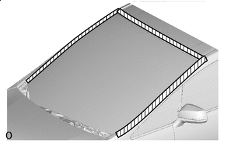
Protective Tape Put protective tape on the body surface around the windshield glass.
-
w/ Windshield Deicer System:
Disconnect the connector.
-
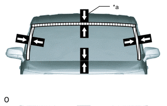
*a Matchmarks When reusing the windshield glass:
Place adhesive tape on the windshield glass and body panel and use a pen to place matchmarks for installation.
-
Install the suction cups to the windshield glass.
-
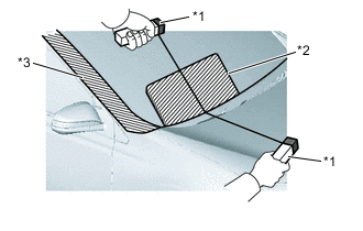
*1 Handles *2 Plastic Sheet *3 Protective Tape Tie objects that can serve as handles (for example, wooden blocks) to both wire ends.
Note
-
When separating the glass from the vehicle, be careful not to damage the vehicle paint or interior/exterior ornaments.
-
To prevent the instrument panel from being scratched when removing the glass, place a plastic sheet between the piano wire and instrument panel.
-
-
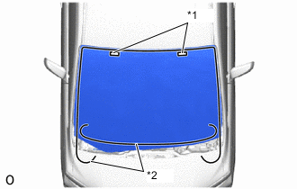
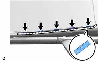
*1 Stopper *2 Piano Wire Insert a piano wire (approx. 0.6 mm) at the locations shown in the illustration.
-
Pull on the ends of the piano wire alternately and leave the stoppers when cutting through the adhesive.
Note
-
Do not forcefully brush the piano wire against the windshield glass.
-
Be careful as the piano wire will break if it crosses itself.
-
-
Using suction cups, detach the 2 windshield glass stoppers to remove the windshield glass.
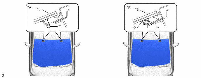
*A for 1-piece Type *B for 2-piece Type *1 Windshield Glass Stopper *2 No. 2 Windshield Glass Stopper *3 Windshield Glass - - Note
-
The windshield glass stopper and No. 2 windshield glass stoppers are installed on the windshield glass as shown in the illustration. Be careful not to damage the windshield glass when cutting off the adhesive.
-
To prevent the windshield glass from falling when performing this operation, be sure to hold the windshield glass using suction cups.
Tech Tips
Depending on the vehicle, either 1-piece or 2-piece type stoppers may be present.
-
-
-
REMOVE NO. 3 WINDSHIELD OUTSIDE MOULDING CLIP
Tech Tips
-
Perform the following procedure if replacing the No. 3 windshield outside moulding clip.
-
Use the same procedure for the other clips.
-
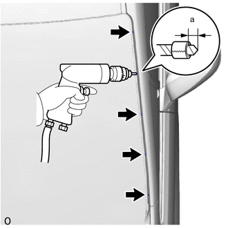
Put a 5 mm drill bit into a drill.
Standard Area Measurement a 5.0 mm (0.1969 in.) -
Wind tape around the drill bit approximately 5 mm from the tip of the drill.
Tech Tips
Tape the 5 mm drill bit to prevent the drill bit from going too deep.
-
Lightly press the drill against the No. 3 windshield outside moulding clip, grind the flanges of the No. 3 windshield outside moulding clip and remove the No. 3 windshield outside moulding clip.
Note
-
Pressing the drill too firmly will cause the clip to turn and result in the clip not being drilled through.
-
Do not pry the clip with the drill because this may cause damage to the installation holes of the clip or the drill bit.
-
Be careful as the drilled clip may become hot.
-
-