ROOF HEADLINING INSTALLATION

CAUTION / NOTICE / HINT
Tech Tips
-
Use the same procedure for RHD and LHD vehicles.
-
The procedure listed below is for LHD vehicles.
-
A bolt without a torque specification is shown in the standard bolt chart.
PROCEDURE
-
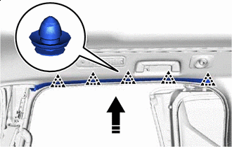
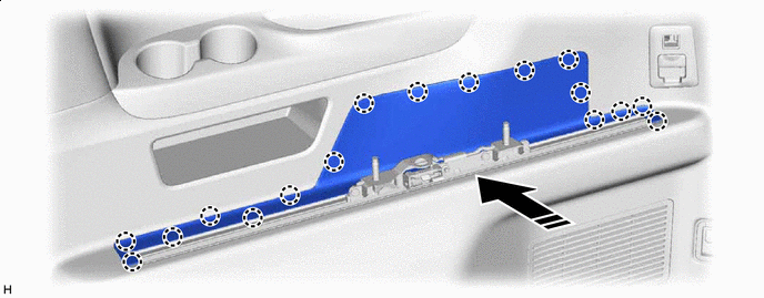
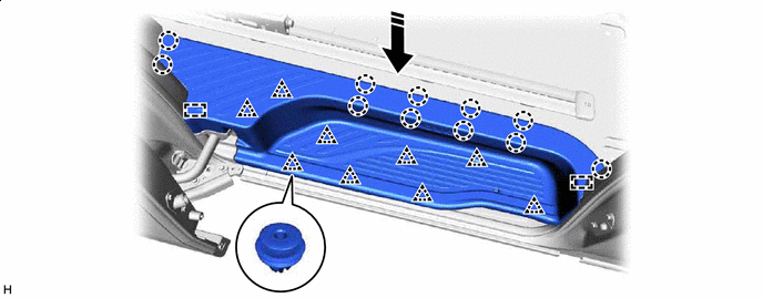
INSTALL FRONT ROOF HEADLINING TRIM SUB-ASSEMBLY (for Normal Roof)
-
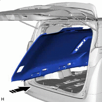

Movement Direction Insert the front roof headlining trim sub-assembly into the cabin from the back door.
Note
-
Check that the corners of the front roof headlining trim sub-assembly are not folded, twisted or otherwise deformed and that none of the mounted parts have fallen off.
-
Make sure that the front roof headlining trim sub-assembly does not get caught on anything as it may become bent or damaged.
-
Do not damage the front roof headlining trim sub-assembly or vehicle interior.
-
-
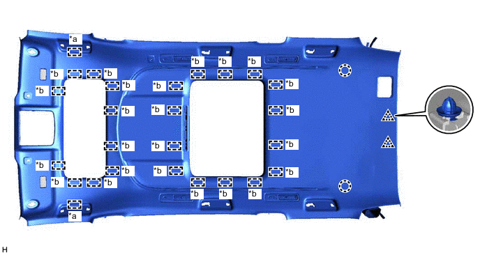
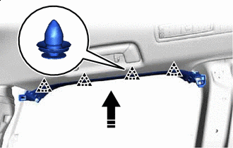
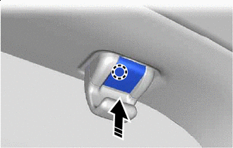
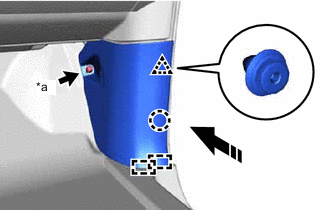
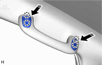
w/o Rear Entertainment System:
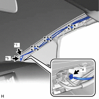
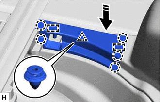
Attach the guide, fastener and clip to install the front roof headlining trim sub-assembly.
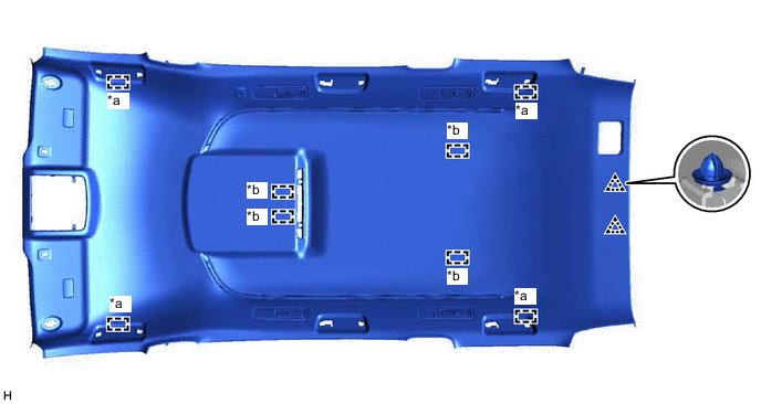
*a Guide *b Fastener -
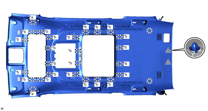
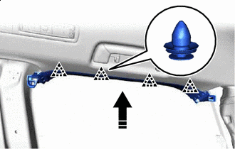
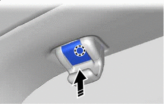
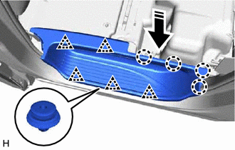
w/ Rear Entertainment System:
Attach the guide, fastener and clip to install the front roof headlining trim sub-assembly.
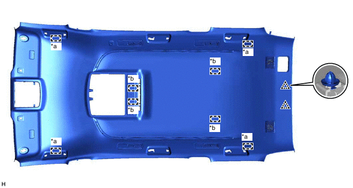
*a Guide *b Fastener -
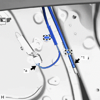
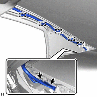
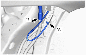
*1 Washer Hose *a Connector Connect the connector and washer hose and attach the clamp to the rear pillar RH.
-
w/ Digital Inner Mirror:
-
Connect the connector.
-
-

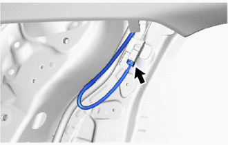
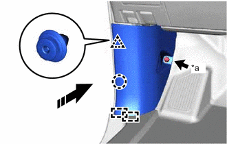
*1 Washer Hose *a Connector *b Bolt Connect the connector and washer hose and attach the clamp to the front pillar RH.
-
Install the bolt.
-
Connect the connector and attach the clamp to the front pillar LH.
-
w/o Digital Inner Mirror:
-
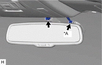
*A w/ Rain Sensor Connect the connector.
-
-
w/ Digital Inner Mirror:
-
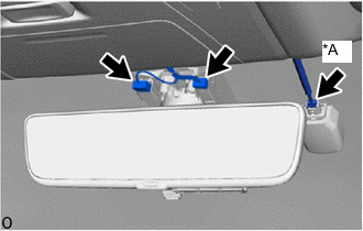
*A w/ Rain Sensor Connect the connector.
-
-
-
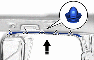
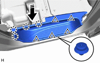
INSTALL FRONT ROOF HEADLINING TRIM SUB-ASSEMBLY (for Sliding Roof)
-
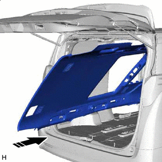
Movement Direction Insert the front roof headlining trim sub-assembly into the cabin from the back door.
Note
-
Check that the corners of the front roof headlining trim sub-assembly are not folded, twisted or otherwise deformed and that none of the mounted parts have fallen off.
-
Make sure that the front roof headlining trim sub-assembly does not get caught on anything as it may become bent or damaged.
-
Do not damage the front roof headlining trim sub-assembly or vehicle interior.
-
-
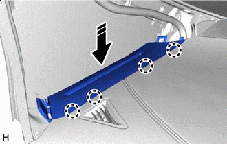
w/o Rear Entertainment System:
Attach the guide, fastener, claw and clip to install the front roof headlining trim sub-assembly.
*a Guide *b Fastener -
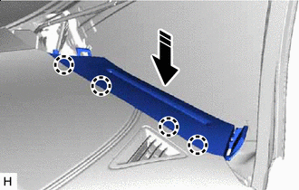
w/ Rear Entertainment System:
Attach the guide, fastener, claw and clip to install the front roof headlining trim sub-assembly.
*a Guide *b Fastener -
*A w/ Digital Inner Mirror *1 Rear Sliding Roof Drain Hose LH Connect the rear sliding roof drain hose LH.
-
w/ Digital Inner Mirror:
-
Connect the connector.
-
-
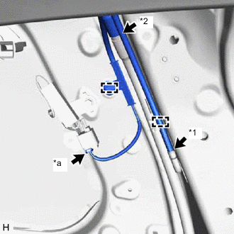
*1 Washer Hose *2 Rear Sliding Roof Drain Hose RH *a Connector Connect the connector, washer hose and rear sliding roof drain hose RH and attach the clamp to the rear pillar RH.
-
*1 Washer Hose *a Connector *b Bolt Connect the connector and washer hose and attach the clamp to the front pillar RH.
-
Install the bolt.
-
Connect the connector and attach the clamp to the front pillar LH.
-
w/o Digital Inner Mirror:
-
*A w/ Rain Sensor Connect the connector.
-
-
w/ Digital Inner Mirror:
-
*A w/ Rain Sensor Connect the connector.
-
-
-
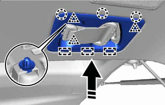
INSTALL TELEVISION BASE (w/ Rear Entertainment System)
-
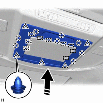
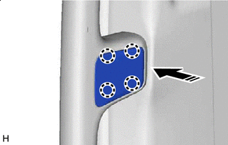
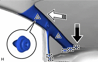
Install in this Direction for 12 Inch:
Attach the guide, claw and clip to install the television base as shown in the illustration.
-
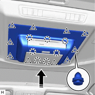
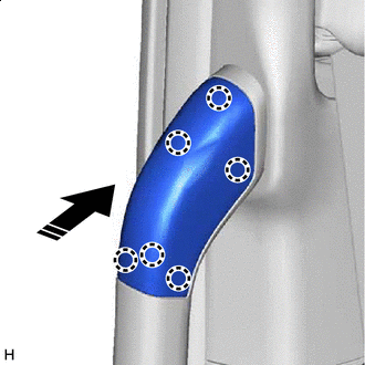
Install in this Direction for 8 Inch:
Attach the claw and clip to install the television base as shown in the illustration.
-
-
INSTALL REAR ROOF SIDE RAIL GARNISH LH
-
Install in this Direction Attach the clip to install the rear roof side rail garnish LH as shown in the illustration.
-
Install in this Direction w/ Sunshade:
Attach the claw as shown in the illustration.
Tech Tips
Use the same procedure for both sunshade hooks.
-
-
INSTALL REAR ROOF SIDE RAIL GARNISH RH
-
Install in this Direction Attach the clip to install the rear roof side rail garnish RH as shown in the illustration.
-
Install in this Direction w/ Sunshade:
Attach the claw as shown in the illustration.
Tech Tips
Use the same procedure for both sunshade hooks.
-
-
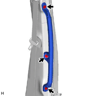
INSTALL FRONT ROOF SIDE RAIL GARNISH LH
-
Install in this Direction Attach the clip to install the front roof side rail garnish LH as shown in the illustration.
-
-
INSTALL FRONT ROOF SIDE RAIL GARNISH RH
-
Install in this Direction Attach the clip to install the front roof side rail garnish RH as shown in the illustration.
-
-
INSTALL NO. 1 COOLER AIR DUCT
-
INSTALL COOLER PLATE
-
INSTALL SEAT BELT ANCHOR COVER
-
Install in this Direction Attach the guide, claw and clip to install the seat belt anchor cover as shown in the illustration.
-
-
INSTALL INTEGRATION CONTROL AND PANEL ASSEMBLY
-
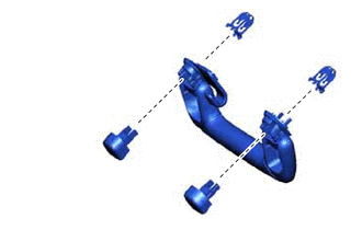
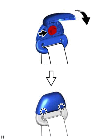
INSTALL REAR ASSIST GRIP ASSEMBLY LH
-
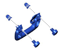
Install the 2 clips and 2 assist grip covers to the rear assist grip.
Tech Tips
Temporarily install the 2 assist grip covers.
-
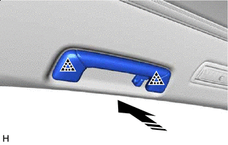
Install in this Direction Attach the clip.
-
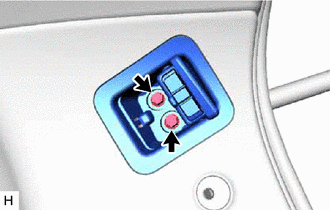
Push in the 2 assist grip covers to install the rear assist grip assembly LH.
-
-
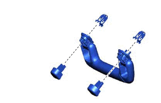
INSTALL REAR ASSIST GRIP ASSEMBLY RH
-
Install the 2 clips and 2 assist grip covers to the rear assist grip.
Tech Tips
Temporarily install the 2 assist grip covers.
-
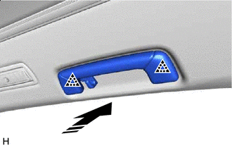
Install in this Direction Attach the clip.
-
Push in the 2 assist grip covers to install the rear assist grip assembly RH.
-
-
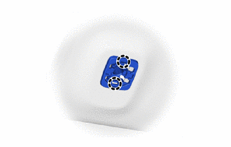
INSTALL ASSIST GRIP SUB-ASSEMBLY
Tech Tips
Use the same procedure for both assist grip sub-assemblies.
-
Install the 2 clips and 2 assist grip covers to the rear assist grip.
Tech Tips
Temporarily install the 2 assist grip covers.
-
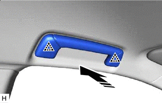
Install in this Direction Attach the clip.
-
Push in the 2 assist grip covers to install the assist grip sub-assembly.
-
-
INSTALL RAIN SENSOR COVER (w/ Rain Sensor)
-
INSTALL INNER REAR VIEW MIRROR STAY HOLDER COVER (w/ EC Mirror)
-
INSTALL INNER REAR VIEW MIRROR STAY HOLDER COVER (w/ Digital Inner Mirror)
-
INSTALL NO. 2 INNER REAR VIEW MIRROR STAY HOLDER COVER (w/ Digital Inner Mirror)
-
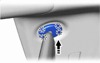
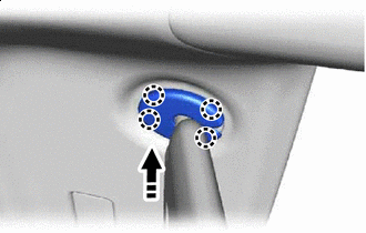
INSTALL VISOR HOLDER
Tech Tips
Use the same procedure for both visor holders.
-
Attach the claw.
-
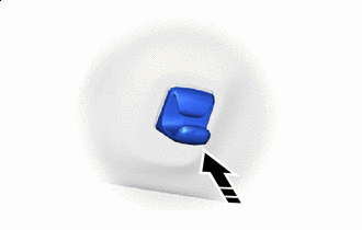
Install in this Direction Push in the visor holder to install it.
-
-
INSTALL VISOR ASSEMBLY LH
-
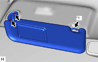
*1 Visor Holder Install the visor assembly LH with the 2 screws.
-
Connect the visor assembly LH to the visor holder.
-
-
INSTALL VISOR ASSEMBLY RH
-
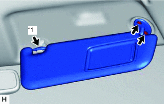
*1 Visor Holder Install the visor assembly RH with the 2 screws.
-
Connect the visor assembly RH to the visor holder.
-
-
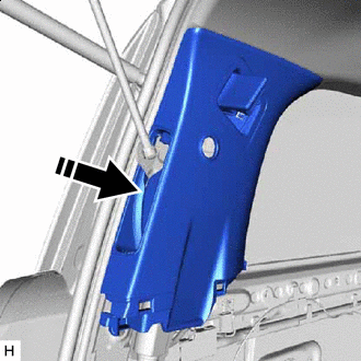
INSTALL VISOR BRACKET COVER LH
-
Install in this Direction Attach the claw to install the visor bracket cover LH as shown in the illustration.
-
-
INSTALL VISOR BRACKET COVER RH
-
Install in this Direction Attach the claw to install the visor bracket cover RH as shown in the illustration.
-
-
INSTALL MAP LIGHT ASSEMBLY
-
for LED Type:
-
for Bulb Type:
-
-
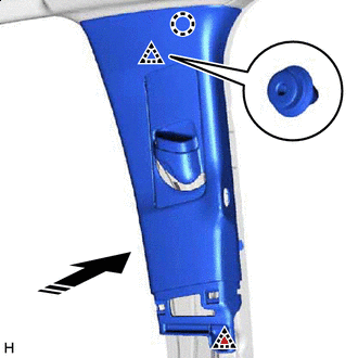
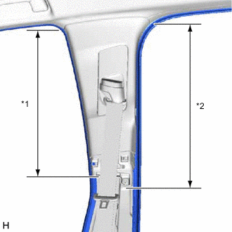
INSTALL INNER UPPER ROOF SIDE GARNISH LH
-
Install in this Direction w/ Power Back Door:
Pass the power back door rod through the inner upper roof side garnish LH.
-
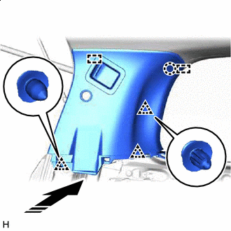
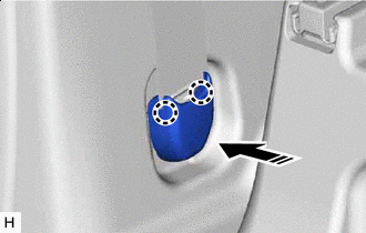
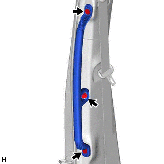
Install in this Direction Attach the guide, claw and clip to install the inner upper roof side garnish LH as shown in the illustration.
-
Install the 2 bolts.
-
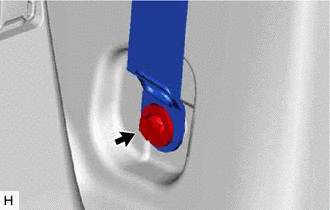
Cover Closing Direction Connect the rear No. 2 seat outer belt assembly LH with the bolt.
- Torque:
- 42 N*m { 428 kgf*cm, 31 ft.*lbf }
-
Attach the claw to close the cover.
-
w/ Power Back Door:
Connect the power back door rod.
-
-
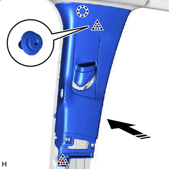
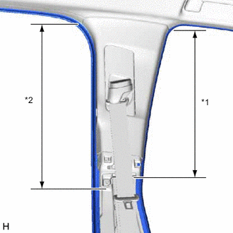
INSTALL INNER UPPER ROOF SIDE GARNISH RH
-
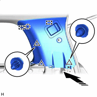
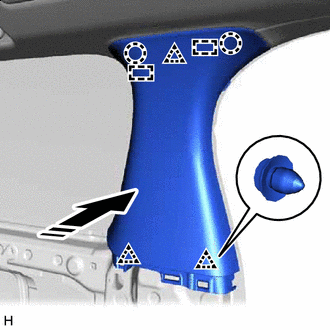
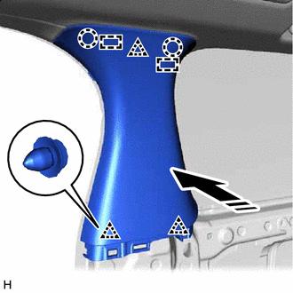
Install in this Direction Attach the guide, claw and clip to install the inner upper roof side garnish RH as shown in the illustration.
-
Install the 2 bolts.
-
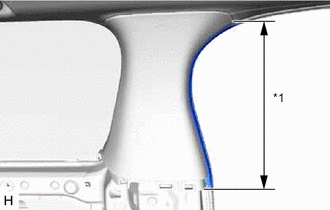
Cover Closing Direction Connect the rear No. 2 seat outer belt assembly RH with the bolt.
- Torque:
- 42 N*m { 428 kgf*cm, 31 ft.*lbf }
-
Attach the claw to close the cover.
-
-
INSTALL BACK DOOR SIDE GARNISH LH (w/ Power Back Door)
-
INSTALL BACK DOOR SERVICE HOLE COVER LH (w/ Power Back Door)
-
INSTALL CENTER BACK DOOR GARNISH (w/ Power Back Door)
-
INSTALL QUARTER LOCK PILLAR GARNISH LH
-
Install in this Direction Attach the guide, claw and clip to install the quarter lock pillar garnish LH as shown in the illustration.
-
*1 No. 1 Slide Door Weatherstrip LH Connect the No. 1 slide door weatherstrip LH in the range shown in the illustration.
-
-
INSTALL QUARTER LOCK PILLAR GARNISH RH
-
Install in this Direction Attach the guide, claw and clip to install the quarter lock pillar garnish RH as shown in the illustration.
-
*1 No. 1 Slide Door Weatherstrip RH Connect the No. 1 slide door weatherstrip RH in the range shown in the illustration.
-
-
INSTALL REAR QUARTER TRIM PANEL ASSEMBLY LH
-
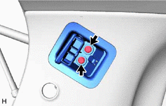
Connect the connector.
-
Attach the claw and clip to install the rear quarter trim panel assembly LH as shown in the illustration.
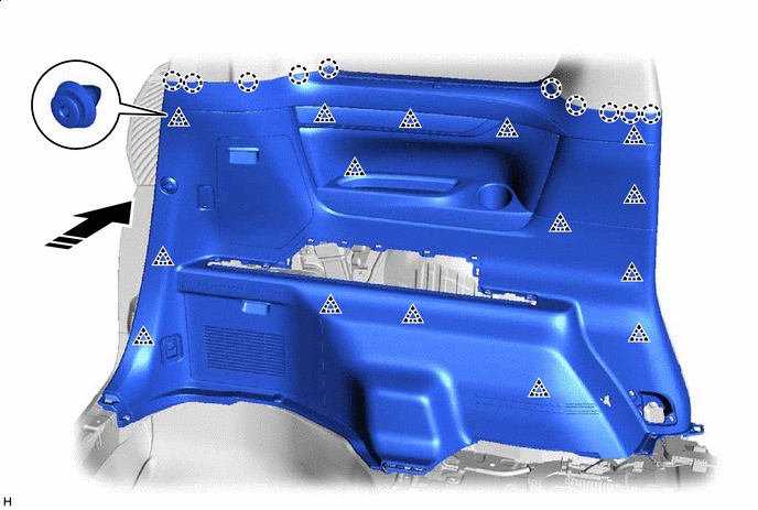
Install in this Direction - - -
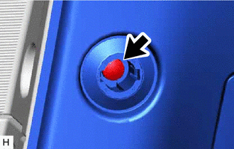
Install the screw.
-
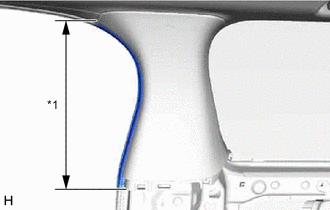
*1 No. 1 Slide Door Weatherstrip LH Connect the No. 1 slide door weatherstrip LH in the range shown in the illustration.
-
-
INSTALL REAR QUARTER TRIM PANEL ASSEMBLY RH
-
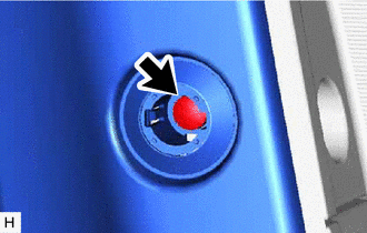
Connect the connector.
-
Attach the claw and clip to install the rear quarter trim panel assembly RH as shown in the illustration.
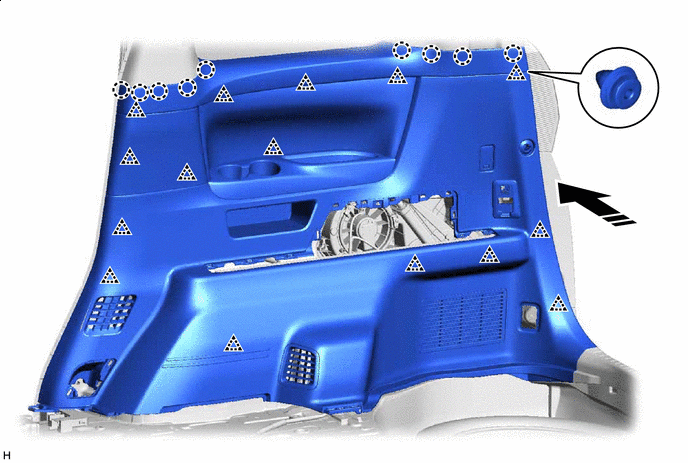
Install in this Direction - - -
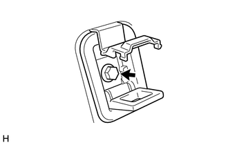
Install the screw.
-
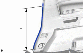
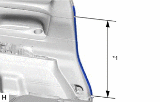
*1 No. 1 Slide Door Weatherstrip RH Connect the No. 1 slide door weatherstrip RH in the range shown in the illustration.
-
-
INSTALL ROPE HOOK ASSEMBLY
Tech Tips
Use the same procedure for both rope hook assemblies.
-
Install the rope hook assembly with the bolt.
-
Attach the claw to close the cover.
-
-
INSTALL NO. 2 LUGGAGE COMPARTMENT TRIM HOOK
-
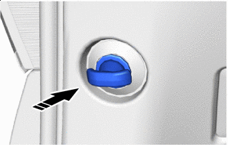
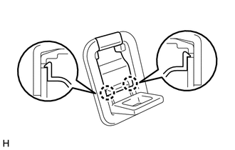
Install in this Direction Turn the end of the No. 2 luggage compartment trim hook horizontal, and then install the No. 2 luggage compartment trim hook.
-
-
INSTALL NO. 1 LUGGAGE COMPARTMENT TRIM HOOK
-
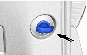
Install in this Direction Turn the end of the No. 1 luggage compartment trim hook horizontal, and then install the No. 1 luggage compartment trim hook.
-
-
INSTALL DECK SIDE GARNISH LH
-
Attach the claw to install the deck side garnish LH as shown in the illustration.
Install in this Direction - -
-
-
INSTALL DECK SIDE GARNISH RH
-
Attach the claw to install the deck side garnish RH as shown in the illustration.
Install in this Direction - -
-
-
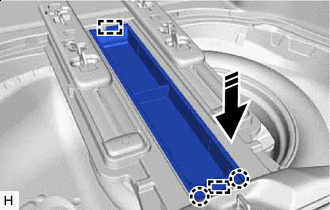
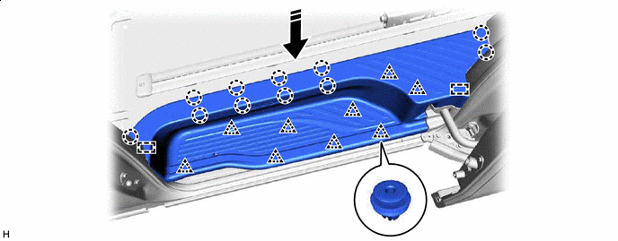
INSTALL REAR UPPER NO. 2 FLOOR BOARD PLATE
-
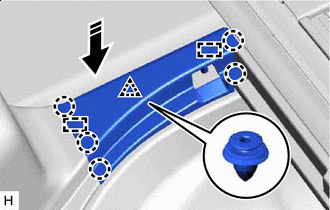
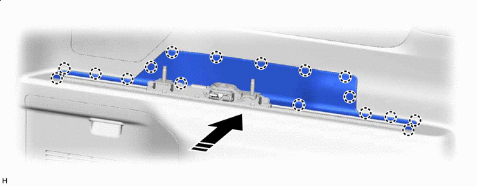
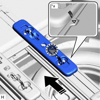
Install in this Direction Attach the guide, claw and clip to install the rear upper No. 2 floor board plate as shown in the illustration.
-
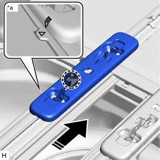
*a Alignment Mark 
Press Position of the Rear Seat Track Slide Stopper Slide Direction Press the part of the rear seat track slide stopper shown in the illustration, slide the rear seat track slide stopper in the direction indicated by the arrow and align the alignment marks.
-
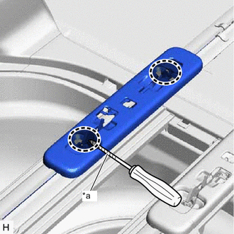
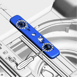
*a Protective Tape Lock Position Using a screwdriver, return the lock of the rear seat track slide stopper to its original condition.
Tech Tips
Tape the screwdriver tip before use.
-
-
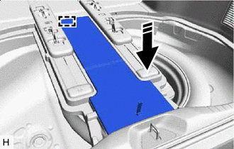
INSTALL REAR UPPER NO. 1 FLOOR BOARD PLATE
-
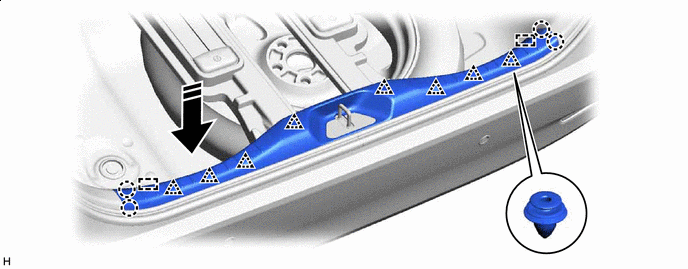
Install in this Direction Attach the guide, claw and clip to install the rear upper No. 1 floor board plate as shown in the illustration.
-
*a Alignment Mark Press Position of the Rear Seat Track Slide Stopper Slide Direction Press the part of the rear seat track slide stopper shown in the illustration, slide the rear seat track slide stopper in the direction indicated by the arrow and align the alignment marks.
-
*a Protective Tape Lock Position Using a screwdriver, return the lock of the rear seat track slide stopper to its original condition.
Tech Tips
Tape the screwdriver tip before use.
-
-
INSTALL BACK DOOR SCUFF PLATE
-
Attach the guide, claw and clip to install the back door scuff plate as shown in the illustration.
Install in this Direction - -
-
-
INSTALL UTILITY BOX SUB-ASSEMBLY
-
Install in this Direction Attach the guide and claw to install the utility box sub-assembly as shown in the illustration.
-
-
INSTALL REAR NO. 3 FLOOR BOARD ASSEMBLY
-
Install in this Direction Attach the guide to install the rear No. 3 floor board assembly as shown in the illustration.
-
-
INSTALL REAR NO. 2 FLOOR BOARD ASSEMBLY
-
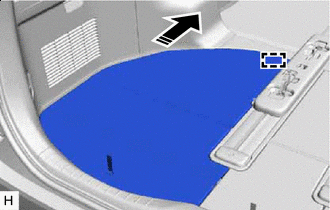
Install in this Direction Attach the guide to install the rear No. 2 floor board assembly as shown in the illustration.
-
-
INSTALL REAR NO. 1 FLOOR BOARD ASSEMBLY
-
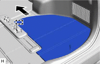
Install in this Direction Attach the guide to install the rear No. 1 floor board assembly as shown in the illustration.
-
-
INSTALL CENTER PILLAR GARNISH LH
Tech Tips
Move the front shoulder belt anchor adjuster and shoulder belt anchor cover to the lowest position and install the center pillar garnish LH.
-
Pass the front seat outer belt floor anchor through the center pillar garnish LH.
-
Install in this Direction Attach the claw and clip to install the center pillar garnish LH as shown in the illustration.
-
*1 Front Door Opening Trim Weatherstrip LH *2 No. 1 Slide Door Weatherstrip LH Connect the front door opening trim weatherstrip LH and No. 1 slide door weatherstrip LH in the range shown in the illustration.
-
-
INSTALL CENTER PILLAR GARNISH RH
Tech Tips
Move the front shoulder belt anchor adjuster and shoulder belt anchor cover to the lowest position and install the center pillar garnish RH.
-
Pass the front seat outer belt floor anchor through the center pillar garnish RH.
-
Install in this Direction Attach the claw and clip to install the center pillar garnish RH as shown in the illustration.
-
*1 Front Door Opening Trim Weatherstrip RH *2 No. 1 Slide Door Weatherstrip RH Connect the front door opening trim weatherstrip RH and No. 1 slide door weatherstrip RH in the range shown in the illustration.
-
-
INSTALL LOWER CENTER PILLAR GARNISH LH
-
Install in this Direction Attach the claw and clip to install the lower center pillar garnish LH as shown in the illustration.
-
Connect the front seat outer belt assembly LH with the bolt.
- Torque:
- 42 N*m { 428 kgf*cm, 31 ft.*lbf }
-
*1 Front Door Opening Trim Weatherstrip LH *2 No. 1 Slide Door Weatherstrip LH Connect the front door opening trim weatherstrip LH and No. 1 slide door weatherstrip LH in the range shown in the illustration.
-
-
INSTALL LOWER CENTER PILLAR GARNISH RH
-
Install in this Direction Attach the claw and clip to install the lower center pillar garnish RH as shown in the illustration.
-
Connect the front seat outer belt assembly RH with the bolt.
- Torque:
- 42 N*m { 428 kgf*cm, 31 ft.*lbf }
-
*1 Front Door Opening Trim Weatherstrip RH *2 No. 1 Slide Door Weatherstrip RH Connect the front door opening trim weatherstrip RH and No. 1 slide door weatherstrip RH in the range shown in the illustration.
-
-
INSTALL OUTER LAP BELT ANCHOR COVER
Tech Tips
Use the same procedure for outer lap belt anchor covers.
-
Install in this Direction Attach the claw to install the outer lap belt anchor cover as shown in the illustration.
-
-
INSTALL NO. 2 ASSIST GRIP
-
Install the No. 2 assist grip with the 3 bolts.
-
-
INSTALL NO. 1 ASSIST GRIP
-
Install the No. 1 assist grip with the 3 bolts.
-
-
INSTALL ASSIST GRIP PLUG
Tech Tips
Use the same procedure for both assist grip plugs.
-
Install in this Direction Attach the claw to install the assist grip plug as shown in the illustration.
-
-
INSTALL ASSIST GRIP PLUG
Tech Tips
Use the same procedure for all assist grip plugs.
-
Install in this Direction Attach the claw to install the assist grip plug as shown in the illustration.
-
-
INSTALL REAR DOOR SCUFF PLATE LH
-
Attach the guide, claw and clip to install the rear door scuff plate LH as shown in the illustration.
Install in this Direction - -
-
-
INSTALL REAR DOOR SCUFF PLATE RH
-
Attach the guide, claw and clip to install the rear door scuff plate RH as shown in the illustration.
Install in this Direction - -
-
-
INSTALL DOOR SCUFF PLATE ASSEMBLY LH
-
Install in this Direction Attach the claw and clip to install the door scuff plate assembly LH as shown in the illustration.
-
-
INSTALL DOOR SCUFF PLATE ASSEMBLY RH
-
Install in this Direction Attach the claw and clip to install the door scuff plate assembly RH as shown in the illustration.
-
-
INSTALL COWL SIDE TRIM BOARD LH
-
*a Cap Nut Install in this Direction Attach the guide, claw and clip to install the cowl side trim board LH as shown in the illustration.
-
Install the cap nut.
-
-
INSTALL COWL SIDE TRIM BOARD RH
-
*a Cap Nut Install in this Direction Attach the guide, claw and clip to install the cowl side trim board RH as shown in the illustration.
-
Install the cap nut.
-
-
INSTALL LOWER FRONT PILLAR GARNISH LH
-
Install in this Direction Attach the claw to install the lower front pillar garnish LH as shown in the illustration.
-
-
INSTALL LOWER FRONT PILLAR GARNISH RH
-
Install in this Direction Attach the claw to install the lower front pillar garnish RH as shown in the illustration.
-
-
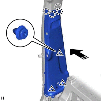
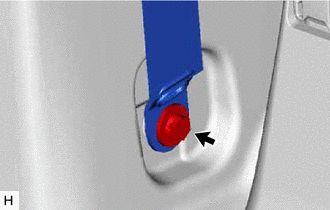
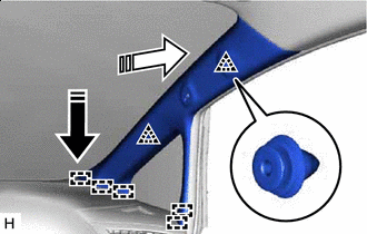
INSTALL FRONT PILLAR GARNISH LH
-
Install in this Direction (1) 
Install in this Direction (2) Attach the guide and clip to install the front pillar garnish LH as shown in the illustration.
-
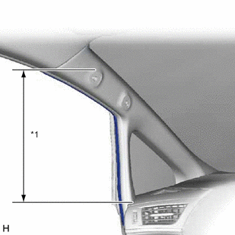
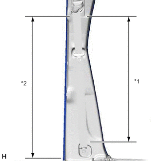
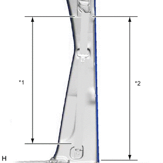
*1 Front Door Opening Trim Weatherstrip LH Connect the front door opening trim weatherstrip LH in the range shown in the illustration.
-
-
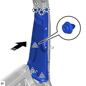
INSTALL FRONT PILLAR GARNISH RH
-
Install in this Direction (1) Install in this Direction (2) Attach the guide and clip to install the front pillar garnish RH as shown in the illustration.
-
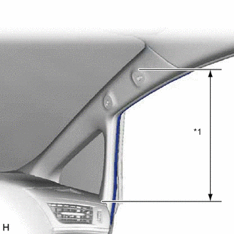
*1 Front Door Opening Trim Weatherstrip RH Connect the front door opening trim weatherstrip RH in the range shown in the illustration.
-
-
INSTALL PILLAR ASSIST GRIP ASSEMBLY
Tech Tips
Use the same procedure for both pillar assist grip assemblies.
-
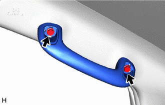
Install the pillar assist grip assembly with the 2 bolts.
-
-
INSTALL ASSIST GRIP PLUG
Tech Tips
Use the same procedure for both assist grip plugs.
-
Install in this Direction Attach the claw to install the 2 assist grip plugs as shown in the illustration.
-
-
INSTALL REAR NO. 2 SEAT ASSEMBLY LH
-
INSTALL REAR NO. 2 SEAT ASSEMBLY RH
-
FILL UP WINDSHIELD WASHER JAR WITH WASHER FLUID
-
INSTALL FRONT FENDER SPLASH SHIELD SUB-ASSEMBLY RH
-
CONNECT CABLE TO NEGATIVE BATTERY TERMINAL
Note
When disconnecting the cable, some systems need to be initialized after the cable is reconnected.
-
CHECK SRS WARNING LIGHT