ROOF HEADLINING REASSEMBLY

CAUTION / NOTICE / HINT
Tech Tips
-
Use the same procedure for RHD and LHD vehicles.
-
The procedure listed below is for LHD vehicles.
PROCEDURE
-
INSTALL SUNSHADE HOOK
Tech Tips
Use the same procedure for all sunshade hooks.
-
Attach the claw to install the sunshade hook.
-
-
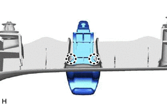
INSTALL REAR SEAT HOOK SUB-ASSEMBLY LH
-
Attach the claw and guide to install the rear seat hook sub-assembly LH.
-
-
INSTALL REAR SEAT HOOK SUB-ASSEMBLY RH
-
Attach the claw and guide to install the rear seat hook sub-assembly RH.
-
-
INSTALL SHOULDER BELT ANCHOR COVER LH
-
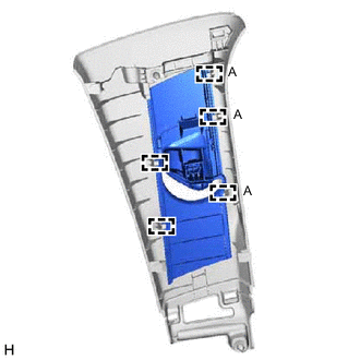
Attach the guide to install the shoulder belt anchor cover LH.
Tech Tips
Install the part starting from guide A shown in the illustration.
-
-
INSTALL SHOULDER BELT ANCHOR COVER RH
-
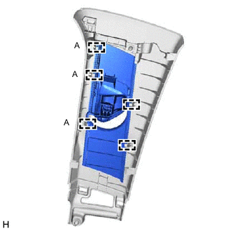
Attach the guide to install the shoulder belt anchor cover RH.
Tech Tips
Install the part starting from guide A shown in the illustration.
-
-
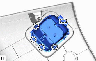
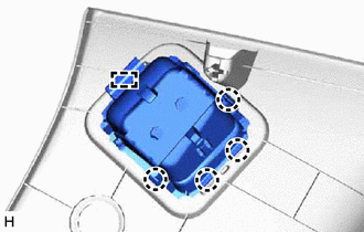
INSTALL QUARTER TRIM JACK COVER SUB-ASSEMBLY
-
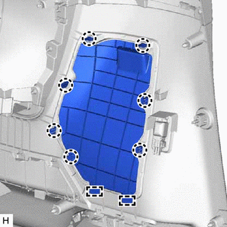
Attach the claw and guide to install the quarter trim jack cover sub-assembly.
-
-
INSTALL QUARTER TRIM COVER
Tech Tips
Use the same procedure for both quarter trim covers.
-
Attach the claw to install the quarter trim cover.
-
-
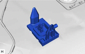
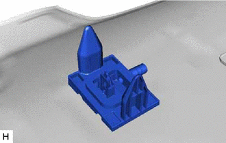
INSTALL REAR SEAT STOPPER
Tech Tips
Use the same procedure for both rear seat stoppers.
-
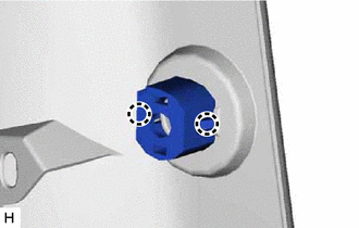
Install the rear seat stopper.
-
-
INSTALL INNER LUGGAGE COMPARTMENT TRIM COVER LH
-
Attach the claw to install the inner luggage compartment trim cover LH.
-
-
INSTALL INNER LUGGAGE COMPARTMENT TRIM COVER RH
-
Attach the claw to install the inner luggage compartment trim cover RH.
-
-
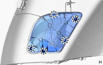
INSTALL SLIDING ROOF HOUSING DRAIN END CAP LH (for Sliding Roof)
-
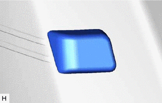
Remove the peeling paper from a new sliding roof housing drain end cap LH and press firmly to install the sliding roof housing drain end cap LH in the position shown in the illustration.
-
-
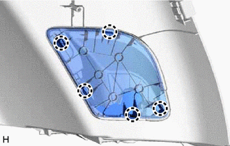
INSTALL SLIDING ROOF HOUSING DRAIN END CAP RH (for Sliding Roof)
-
Remove the peeling paper from a new sliding roof housing drain end cap RH and press firmly to install the sliding roof housing drain end cap RH in the position shown in the illustration.
-
-
INSTALL REAR SLIDING ROOF DRAIN HOSE LH (for Sliding Roof)
-
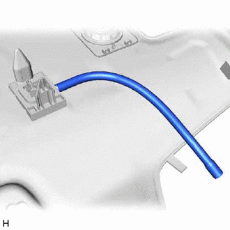
Install the rear sliding roof drain hose LH.
-
-
INSTALL REAR SLIDING ROOF DRAIN HOSE RH (for Sliding Roof)
-
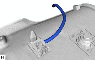
Install the rear sliding roof drain hose RH.
-
-
INSTALL NO. 2 ANTENNA CORD SUB-ASSEMBLY
-
w/o Rear Seat Entertainment System:
-
w/ Rear Seat Entertainment System:
-
-
INSTALL WASHER HOSE
-
Attach the clamp to install the washer hose.
-
-
INSTALL NO. 1 ROOF WIRE
-
for Normal Roof:
-
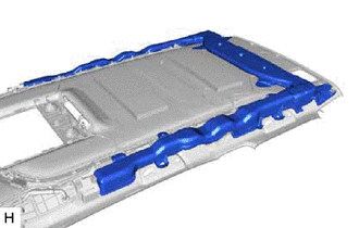
Apply butyl tape as shown in the illustration.
Tech Tips
Place the tape securely so that it is not misaligned or peeling.
-
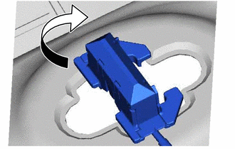
Turn the visor connectors approximately 90° clockwise to install them to the roof headlining trim sub-assembly.
-
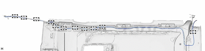
Attach the clamp to install the No. 1 roof wire to the roof headlining trim sub-assembly.
-
Attach the No. 1 roof wire to the butyl tape, and then secure the No. 1 roof wire with pieces of fastening tape.
Tech Tips
-
Adjust the slack of the No. 1 roof wire as shown in the parts of the illustration labeled (A).
-
Make sure that the No. 1 roof wire is securely attached to the roof headlining trim sub-assembly along its entire length and not twisted.
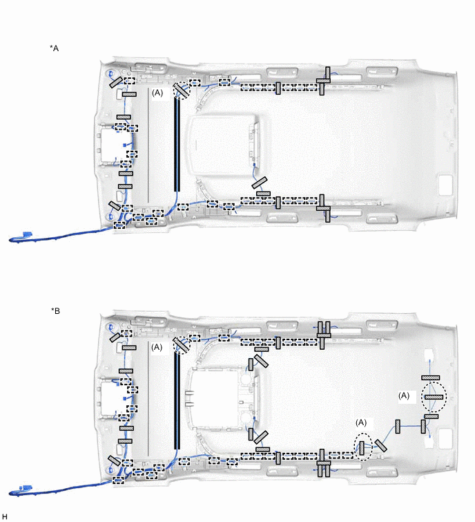
*A w/o Rear Seat Entertainment System *B w/ Rear Seat Entertainment System 
Butyl Tape 
Fastening Tape -
-
Install the duct with adhesive or double-sided tape.
-
-
for Sliding Roof:
-
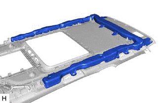
Apply butyl tape as shown in the illustration.
Tech Tips
Place the tape securely so that it is not misaligned or peeling.
-
Turn the visor connectors approximately 90° clockwise to install them to the roof headlining trim sub-assembly.
-
Attach the clamp to install the No. 1 roof wire to the roof headlining trim sub-assembly.
-
Attach the No. 1 roof wire to the butyl tape, and then secure the No. 1 roof wire with pieces of fastening tape.
Tech Tips
-
Adjust the slack of the No. 1 roof wire as shown in the parts of the illustration labeled (A).
-
Make sure that the No. 1 roof wire is securely attached to the roof headlining trim sub-assembly along its entire length and not twisted.
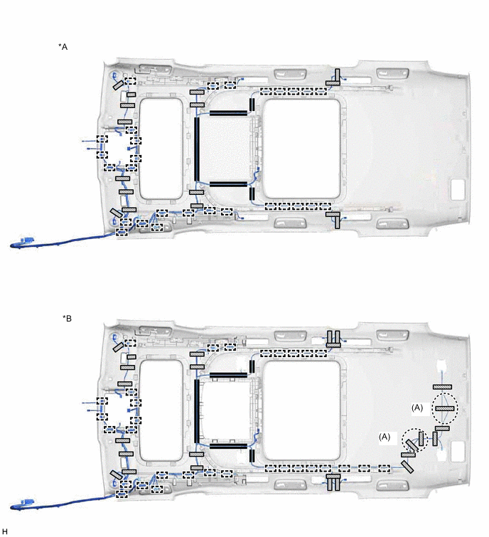
*A w/o Rear Seat Entertainment System *B w/ Rear Seat Entertainment System Butyl Tape Fastening Tape -
-
Install the duct with adhesive or double-sided tape.
-
-
-
INSTALL NO. 2 ROOF HEADLINING RETAINER BRACKET (w/ Rear Ion Generator)
-
INSTALL REAR AIR DUCT SUB-ASSEMBLY (w/ Rear Ion Generator)
-
INSTALL NO. 2 ION GENERATOR SUB-ASSEMBLY (w/ Rear Ion Generator)
-
INSTALL ROOM LIGHT CONTROL RELAY
-
INSTALL NO. 2 INTERIOR ILLUMINATION LIGHT SUB-ASSEMBLY
-
INSTALL INTERIOR ILLUMINATION LIGHT SUB-ASSEMBLY
-
INSTALL NO. 2 SPOT LIGHT ASSEMBLY LH (for Reading Light)
-
INSTALL NO. 2 SPOT LIGHT ASSEMBLY RH (for Reading Light)
-
INSTALL SPOT LIGHT ASSEMBLY LH
-
for LED Type:
-
for Bulb Type:
-
-
INSTALL SPOT LIGHT ASSEMBLY RH
-
for LED Type:
-
for Bulb Type:
-
-
INSTALL CENTER ROOF SPEAKER GRILLE (w/ Rear Seat Entertainment System)
-
for Normal Roof, for Front Side:
-
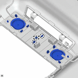
Attach the claw and guide to install the center roof speaker grille.
-
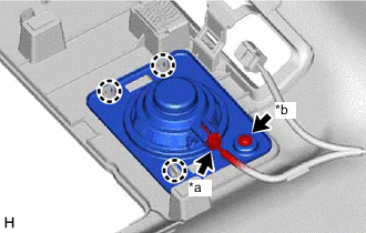
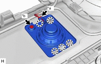
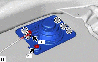
*a Connector *b Screw Attach the claw to install the roof speaker assembly (for LH Side).
-
Connect the connector.
-
Install the screw.
-
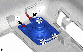
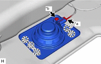
*a Connector *b Screw Attach the claw to install the roof speaker assembly (for RH Side).
-
Connect the connector.
-
Install the screw.
-
-
-
INSTALL ROOF SPEAKER GRILLE LH (w/ Rear Seat Entertainment System)
-
for Normal Roof, for Rear Side:
-
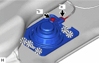
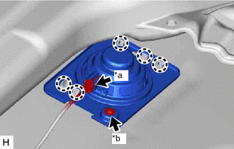
*a Connector *b Screw Attach the claw to install the roof speaker assembly and roof speaker grille LH.
-
Connect the connector.
-
Install the screw.
-
-
for Sliding Roof, for Front Side:
-
*a Connector *b Screw Attach the claw to install the roof speaker assembly and roof speaker grille LH.
-
Connect the connector.
-
Install the screw.
-
-
for Sliding Roof, for Rear Side:
-
*a Connector *b Screw Attach the claw to install the roof speaker assembly and roof speaker grille LH.
-
Connect the connector.
-
Install the screw.
-
-
-
INSTALL ROOF SPEAKER GRILLE RH (w/ Rear Seat Entertainment System)
-
for Normal Roof, for Rear Side:
-
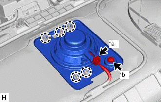
*a Connector *b Screw Attach the claw to install the roof speaker assembly and roof speaker grille RH.
-
Connect the connector.
-
Install the screw.
-
-
for Sliding Roof, for Front Side:
-
*a Connector *b Screw Attach the claw to install the roof speaker assembly and roof speaker grille RH.
-
Connect the connector.
-
Install the screw.
-
-
for Sliding Roof, for Rear Side:
-
*a Connector *b Screw Attach the claw to install the roof speaker assembly and roof speaker grille RH.
-
Connect the connector.
-
Install the screw.
-
-
-
INSTALL VANITY LIGHT ASSEMBLY
Tech Tips
Use the same procedure for both vanity light assemblies.
-
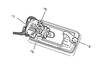
*1 Bulb Holder *a Claw A *b Claw B Attach the claw A of the vanity light assembly to temporarily install the vanity light assembly to the front roof headlining trim sub-assembly.
-
Attach the claw B of the bulb holder to install the vanity light assembly.
-