ROOF HEADLINING REMOVAL

CAUTION / NOTICE / HINT
Tech Tips
-
Use the same procedure for RHD and LHD vehicles.
-
The procedure listed below is for LHD vehicles.
The necessary procedures (adjustment, calibration, initialization or registration) that must be performed after parts are removed, installed or replaced during the front roof headlining sub-assembly removal/installation are shown below.
| Replacement Part or Procedure | Necessary Procedures | Effects/Inoperative when not Performed | Link |
|---|---|---|---|
| Disconnect cable from negative battery terminal | Drive the vehicle until stop and start control is permitted (approximately 5 to 60 minutes) | Stop and Start System (for 2AR-FE) | |
| Stop and Start System (for 2GR-FKS) | |||
| Memorize steering angle neutral point | Panoramic View Monitor System | ||
| Initialize back door lock | Power Door Lock Control System | ||
| Initialize servo motor | Air Conditioning System | ||
| Reset slide door close position | Power Slide Door System | ||
| Reset back door close position | Power Back Door System |
CAUTION:
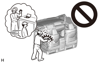
Some of these service operations affect the SRS airbag system. Read the precautionary notices concerning the SRS airbag system before servicing.
PROCEDURE
-
PRECAUTION
Note
After turning the engine switch off, waiting time may be required before disconnecting the cable from the battery terminal. Therefore, make sure to read the disconnecting the cable from the battery terminal notice before proceeding with work.
-
DISCONNECT CABLE FROM NEGATIVE BATTERY TERMINAL
CAUTION:
-
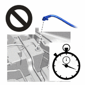
Wait at least 90 seconds after disconnecting the cable from the negative (-) battery terminal to disable the SRS system.
-
If the airbag deploys for any reason, it may cause a serious accident.
Note
When disconnecting the cable, some systems need to be initialized after the cable is reconnected.
-
-
REMOVE FRONT FENDER SPLASH SHIELD SUB-ASSEMBLY RH
-
DRAIN WINDSHIELD WASHER FLUID
-
REMOVE REAR NO. 2 SEAT ASSEMBLY LH
-
REMOVE REAR NO. 2 SEAT ASSEMBLY RH
-
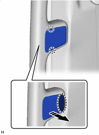
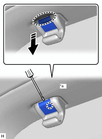
REMOVE ASSIST GRIP PLUG
Tech Tips
Use the same procedure for both assist grip plugs.
-
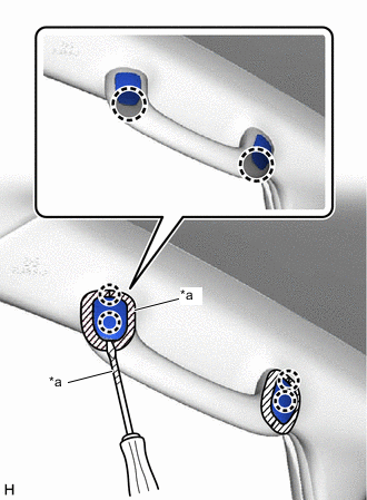
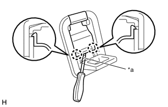
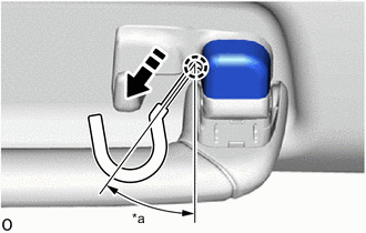
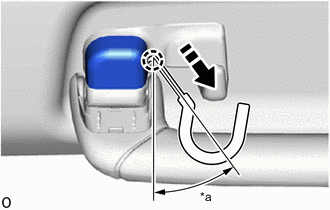
*a Protective Tape 
Insert Thin-bladed Screwdriver Here Put protective tape around the assist grip plug.
-
Insert a thin-bladed screwdriver at the position shown in the illustration and detach the claw and remove the 2 assist grip plugs.
Tech Tips
Tape the thin-bladed screwdriver tip before use.
-
-
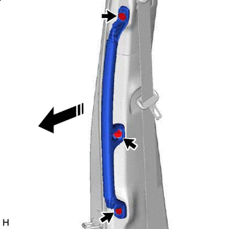
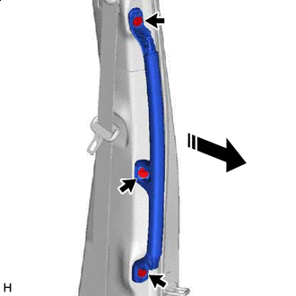
REMOVE PILLAR ASSIST GRIP ASSEMBLY
Tech Tips
Use the same procedure for both pillar assist grip assemblies.
-
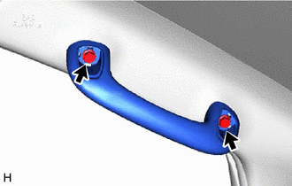
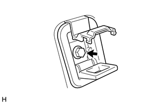
Remove the 2 bolts and pillar assist grip assembly.
-
-
REMOVE FRONT PILLAR GARNISH LH
-
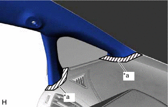
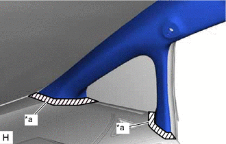
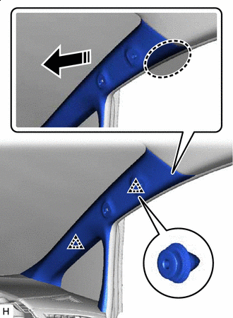
*a Protective Tape Put protective tape around the front pillar garnish LH.
-
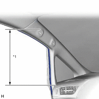
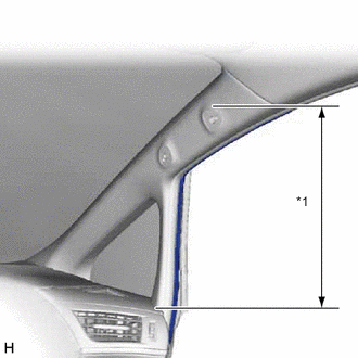
*1 Front Door Opening Trim Weatherstrip LH Disconnect the front door opening trim weatherstrip LH in the range shown in the illustration.
-
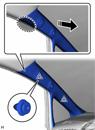
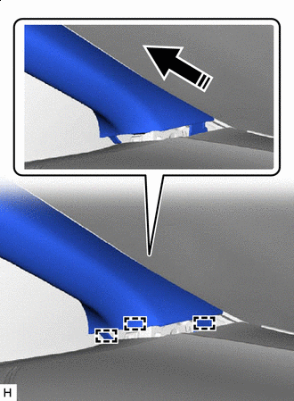
Place Hand Here 
Remove in this Direction Place your hand at the position shown in the illustration and pull in the direction indicated by the arrow to detach the clip.
-
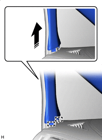
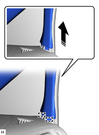
Remove in this Direction Pull up the rear of the front pillar garnish LH in the direction indicated by the arrow shown in the illustration to detach the guide.
-
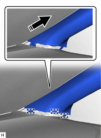
Remove in this Direction Pull up the front of the front pillar garnish LH in the direction indicated by the arrow shown in the illustration to detach the guide and remove the front pillar garnish LH.
-
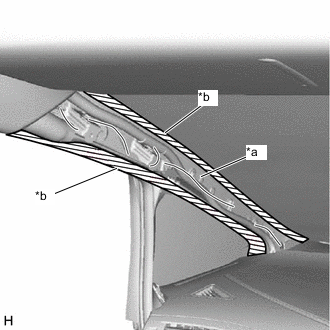
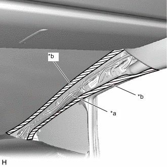
*a Protective Cover *b Adhesive Tape Protect the curtain shield airbag assembly LH.
-
Completely cover the curtain shield airbag assembly LH with a cloth or nylon sheet and secure the ends of the cover with adhesive tape as shown in the illustration.
Note
Cover the curtain shield airbag assembly LH with a protective cover as soon as the front pillar garnish LH is removed.
-
-
-
REMOVE FRONT PILLAR GARNISH RH
-
*a Protective Tape Put protective tape around the front pillar garnish RH.
-
*1 Front Door Opening Trim Weatherstrip RH Disconnect the front door opening trim weatherstrip RH in the range shown in the illustration.
-
Place Hand Here Remove in this Direction Place your hand at the position shown in the illustration and pull in the direction indicated by the arrow to detach the clip.
-
Remove in this Direction Pull up the rear of the front pillar garnish RH in the direction indicated by the arrow shown in the illustration to detach the guide.
-
Remove in this Direction Pull up the front of the front pillar garnish RH in the direction indicated by the arrow shown in the illustration to detach the guide and remove the front pillar garnish RH.
-
*a Protective Cover *b Adhesive Tape Protect the curtain shield airbag assembly RH.
-
Completely cover the curtain shield airbag assembly RH with a cloth or nylon sheet and secure the ends of the cover with adhesive tape as shown in the illustration.
Note
Cover the curtain shield airbag assembly RH with a protective cover as soon as the front pillar garnish RH is removed.
-
-
-
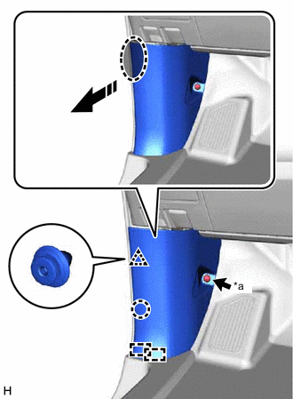
REMOVE LOWER FRONT PILLAR GARNISH LH
-
*a Protective Tape Place Hand Here Remove in this Direction Put protective tape around the lower front pillar garnish LH.
-
Place your hand at the position shown in the illustration and pull in the direction indicated by the arrow to detach the claw.
-
Remove in this Direction Place your hand in the gap created during the above procedure and pull in the direction indicated by the arrows shown in the illustration to detach the claw and remove the lower front pillar garnish LH.
-
-
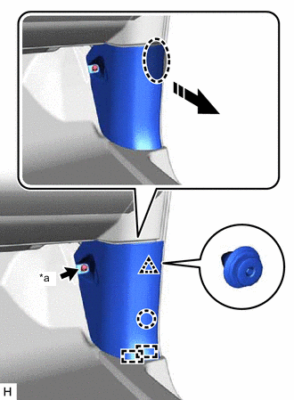
REMOVE LOWER FRONT PILLAR GARNISH RH
-
*a Protective Tape Place Hand Here Remove in this Direction Put protective tape around the lower front pillar garnish RH.
-
Place your hand at the position shown in the illustration and pull in the direction indicated by the arrow to detach the claw.
-
Remove in this Direction Place your hand in the gap created during the above procedure and pull in the direction indicated by the arrows shown in the illustration to detach the claw and remove the lower front pillar garnish RH.
-
-
REMOVE COWL SIDE TRIM BOARD LH
-
*a Cap Nut Place Hand Here Remove in this Direction Remove the cap nut.
-
Place your hand at the position shown in the illustration and pull in the direction indicated by the arrow to detach the claw, clip and guide and remove the cowl side trim board LH.
-
-
REMOVE COWL SIDE TRIM BOARD RH
-
*a Cap Nut Place Hand Here Remove in this Direction Remove the cap nut.
-
Place your hand at the position shown in the illustration and pull in the direction indicated by the arrow to detach the claw, clip and guide and remove the cowl side trim board RH.
-
-
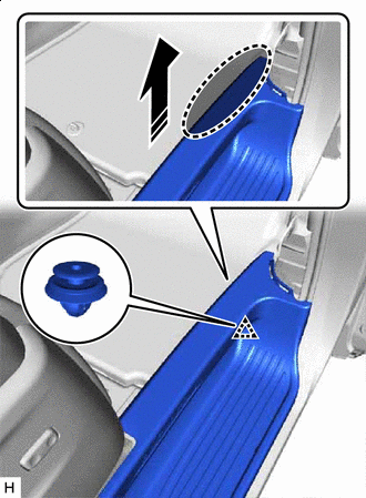
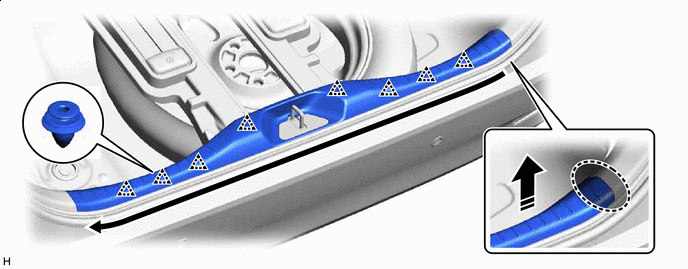
REMOVE DOOR SCUFF PLATE ASSEMBLY LH
-
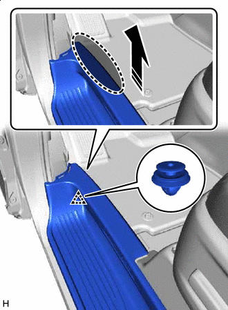
Place Hand Here Remove in this Direction Place your hand at the position shown in the illustration and pull in the direction indicated by the arrow to detach the clip.
-
Place Hand Here Remove in this Direction Place your hand in the gap shown in the illustration created during the above procedure and pull in the direction indicated by the arrow to detach the claw and clip and remove the door scuff plate assembly LH.
-
-
REMOVE DOOR SCUFF PLATE ASSEMBLY RH
-
Place Hand Here Remove in this Direction Place your hand at the position shown in the illustration and pull in the direction indicated by the arrow to detach the clip.
-
Place Hand Here Remove in this Direction Place your hand in the gap shown in the illustration created during the above procedure and pull in the direction indicated by the arrow to detach the claw and clip and remove the door scuff plate assembly RH.
-
-
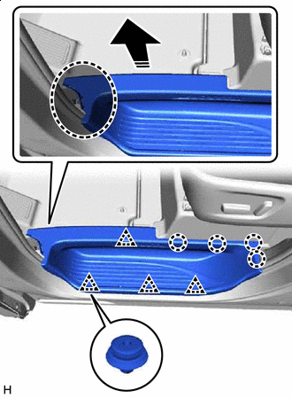
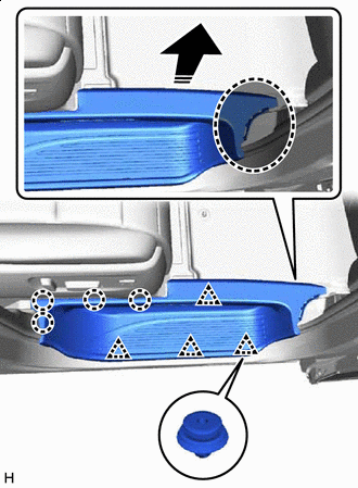
REMOVE REAR DOOR SCUFF PLATE LH
-
Slide the rear No. 1 seat to the rearmost position.
-
Place Hand Here Remove in this Direction Place your hand at the position shown in the illustration and pull in the direction indicated by the arrow to detach the claw, clip and guide.
-
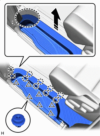
Slide the rear No. 1 seat to the frontmost position.
-
Place Hand Here Remove in this Direction Place your hand at the position shown in the illustration and pull in the direction indicated by the arrow to detach the claw, clip and guide and remove the rear door scuff plate LH.
-
-
REMOVE REAR DOOR SCUFF PLATE RH
-
Slide the rear No. 1 seat to the rearmost position.
-
Place Hand Here Remove in this Direction Place your hand at the position shown in the illustration and pull in the direction indicated by the arrow to detach the claw, clip and guide.
-
Slide the rear No. 1 seat to the frontmost position.
-
Place Hand Here Remove in this Direction Place your hand at the position shown in the illustration and pull in the direction indicated by the arrow to detach the claw, clip and guide and remove the rear door scuff plate RH.
-
-
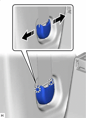
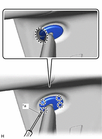
REMOVE ASSIST GRIP PLUG
Tech Tips
Use the same procedure for all assist grip plugs.
-
*a Protective Tape Insert Thin-bladed Screwdriver Here Remove in this Direction Put protective tape around the assist grip plug.
-
Insert a thin-bladed screwdriver at the position shown in the illustration, open the assist grip plug toward the vehicle exterior and rotate it in the direction indicated by the arrow to detach the claw and remove the assist grip plug.
Tech Tips
Tape the thin-bladed screwdriver tip before use.
-
-
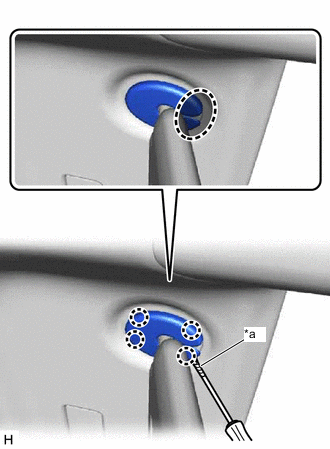
REMOVE ASSIST GRIP PLUG
Tech Tips
Use the same procedure for both assist grip plugs.
-
*a Protective Tape Insert Thin-bladed Screwdriver Here Put protective tape around the assist grip plug.
-
Insert a thin-bladed screwdriver at the position shown in the illustration and detach the claw.
Tech Tips
Tape the thin-bladed screwdriver tip before use.
-
Place finger here Remove in this Direction Place your finger in the gap shown in the illustration created during the above procedure and pull in the direction indicated by the arrow to detach the claw and remove the assist grip plug.
-
-
REMOVE NO. 2 ASSIST GRIP
-
Remove in this Direction Remove the 3 bolts.
-
Pull in the direction indicated by the arrow shown in the illustration to remove the No. 2 assist grip.
-
-
REMOVE NO. 1 ASSIST GRIP
-
Remove in this Direction Remove the 3 bolts.
-
Pull in the direction indicated by the arrow shown in the illustration to remove the No. 1 assist grip.
-
-
REMOVE OUTER LAP BELT ANCHOR COVER
Tech Tips
Use the same procedure for both outer lap belt anchor covers.
-
Outer Lap Belt Anchor Cover Opening Direction Open the outer lap belt anchor cover in the direction indicated by the arrows shown in the illustration to detach the claw, and then remove the outer lap belt anchor cover.
-
-
REMOVE LOWER CENTER PILLAR GARNISH LH
-
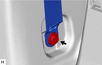
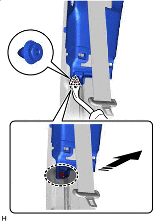
Remove the bolt and disconnect the front seat outer belt assembly LH.
-
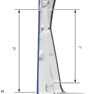
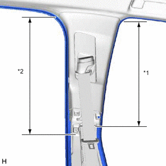
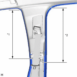
*1 Front Door Opening Trim Weatherstrip LH *2 No. 1 Slide Door Weatherstrip LH Disconnect the front door opening trim weatherstrip LH and No. 1 slide door weatherstrip LH in the range shown in the illustration.
-
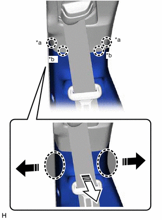
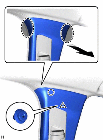
*a Claw A *b Claw B Place Hand Here Lower Center Pillar Garnish LH Opening Direction 
Remove in this Direction Place your hand at the position shown in the illustration and open the lower center pillar garnish LH in the direction indicated by the arrows to detach claw A.
-
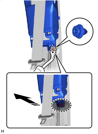
Place your hands in the gaps created during the above procedure and pull in the direction indicated by the arrows shown in the illustration to detach claw B.
-
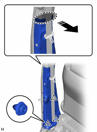
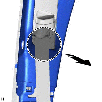
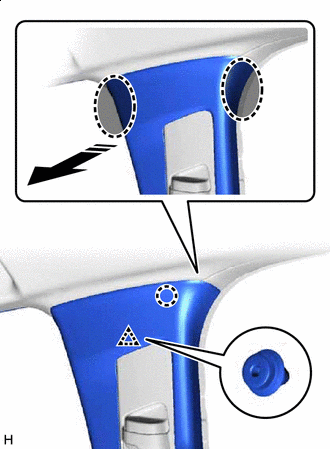
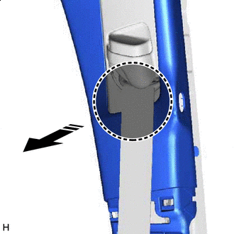
Place Hand Here Remove in this Direction Place your hand in the gap shown in the illustration created during the above procedure and pull in the direction indicated by the arrow to detach the clip and remove the lower center pillar garnish LH.
-
-
REMOVE LOWER CENTER PILLAR GARNISH RH
-
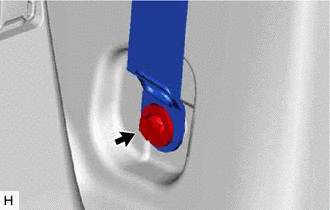
Remove the bolt and disconnect the front seat outer belt assembly RH.
-
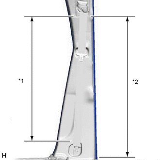
*1 Front Door Opening Trim Weatherstrip RH *2 No. 1 Slide Door Weatherstrip RH Disconnect the front door opening trim weatherstrip RH and No. 1 slide door weatherstrip RH in the range shown in the illustration.
-
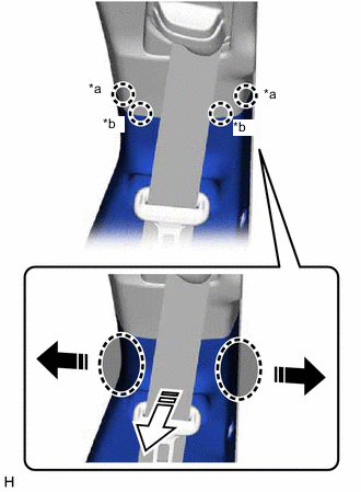
*a Claw A *b Claw B Place Hand Here Lower Center Pillar Garnish RH Opening Direction Remove in this Direction Place your hand at the position shown in the illustration and open the lower center pillar garnish RH in the direction indicated by the arrows to detach claw A.
-
Place your hands in the gaps created during the above procedure and pull in the direction indicated by the arrows shown in the illustration to detach claw B.
-
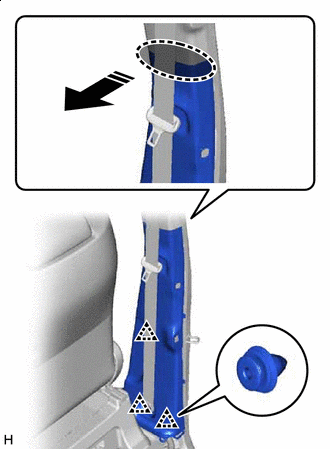
Place Hand Here Remove in this Direction Place your hand in the gap shown in the illustration created during the above procedure and pull in the direction indicated by the arrow to detach the clip and remove the lower center pillar garnish RH.
-
-
REMOVE CENTER PILLAR GARNISH LH
-
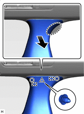
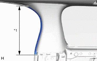
*1 Front Door Opening Trim Weatherstrip LH *2 No. 1 Slide Door Weatherstrip LH Disconnect the front door opening trim weatherstrip LH and No. 1 slide door weatherstrip LH in the range shown in the illustration.
-
Insert Clip Remover Here Remove in this Direction Insert clip remover at the position shown in the illustration and pull in the direction indicated by the arrow to detach the clip.
-
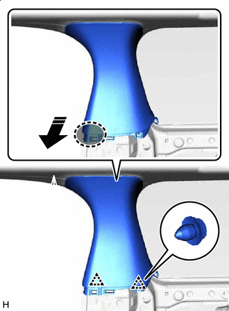
Place Hand Here Remove in this Direction Place your hand at the position shown in the illustration and pull in the direction indicated by the arrow to detach the claw and clip.
-
Pass-through Position of Front Seat Outer Belt Assembly LH Remove in this Direction Pass the front seat outer belt floor anchor through the center pillar garnish LH, and remove the center pillar garnish LH.
-
-
REMOVE CENTER PILLAR GARNISH RH
-
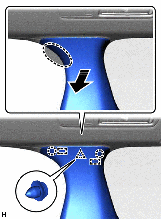
*1 Front Door Opening Trim Weatherstrip RH *2 No. 1 Slide Door Weatherstrip RH Disconnect the front door opening trim weatherstrip RH and No. 1 slide door weatherstrip RH in the range shown in the illustration.
-
Insert Clip Remover Here Remove in this Direction Insert clip remover at the position shown in the illustration and pull in the direction indicated by the arrow to detach the clip.
-
Place Hand Here Remove in this Direction Place your hand at the position shown in the illustration and pull in the direction indicated by the arrow to detach the claw and clip.
-
Pass-through Position of Front Seat Outer Belt Assembly RH Remove in this Direction Pass the front seat outer belt floor anchor through the center pillar garnish RH, and remove the center pillar garnish RH.
-
-
REMOVE REAR NO. 2 FLOOR BOARD ASSEMBLY
-
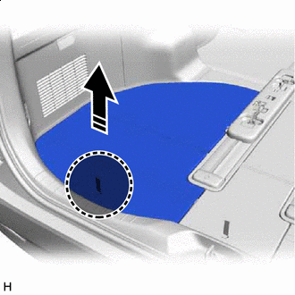
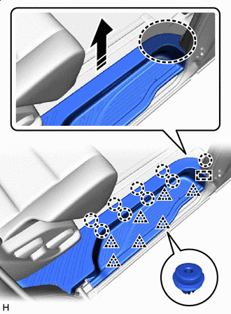
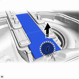
Place Hand Here Remove in this Direction Grasp the handle at the position shown in the illustration and pull up in the direction indicated by the arrow to raise the rear No. 2 floor board assembly.
-
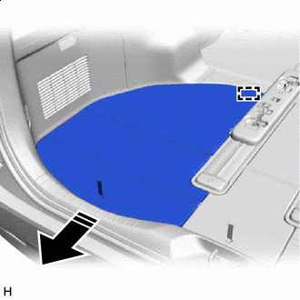
Remove in this Direction Pull in the direction indicated by the arrow shown in the illustration to detach the guide and remove the rear No. 2 floor board assembly.
-
-
REMOVE REAR NO. 1 FLOOR BOARD ASSEMBLY
-
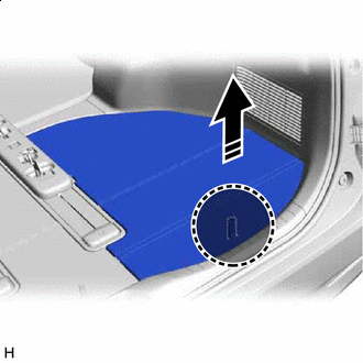
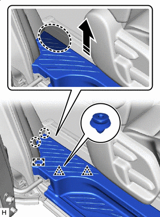
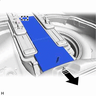
Place Hand Here Remove in this Direction Grasp the handle at the position shown in the illustration and pull up in the direction indicated by the arrow to raise the rear No. 1 floor board assembly.
-
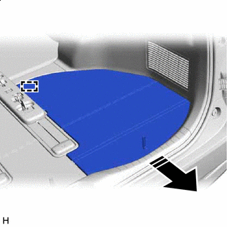
Remove in this Direction Pull in the direction indicated by the arrow shown in the illustration to detach the guide and remove the rear No. 1 floor board assembly.
-
-
REMOVE REAR NO. 3 FLOOR BOARD ASSEMBLY
-
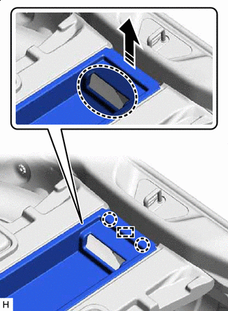
Place Hand Here Remove in this Direction Grasp the handle at the position shown in the illustration and pull up in the direction indicated by the arrow to raise the rear No. 3 floor board assembly.
-
Remove in this Direction Pull in the direction indicated by the arrow shown in the illustration to detach the guide and remove the rear No. 3 floor board assembly.
-
-
REMOVE UTILITY BOX SUB-ASSEMBLY
-
Place Hand Here Remove in this Direction Place your hand at the position shown in the illustration and pull in the direction indicated by the arrow to detach the claw and guide.
-
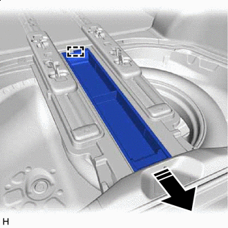
Remove in this Direction Pull in the direction indicated by the arrow shown in the illustration to remove the utility box sub-assembly.
-
-
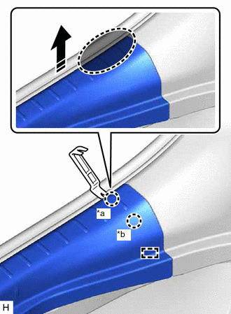
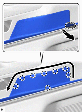
REMOVE BACK DOOR SCUFF PLATE
-

*a Claw A *b Claw B Insert Moulding Remover B Here Remove in this Direction Insert moulding remover B at the position shown in the illustration and pull the moulding remover B towerd the rear of the vehicle to detach the claw A.
-
Pull in the direction indicated by the arrow shown in the illustration to detach claw B and the guide.
-
Place your hand in the gap created during the above procedure and pull in the direction indicated by the arrow to detach the clip as shown in the illustration.
Place Hand Here Remove in this Direction 
Order of Removal - - -
*a Claw A *b Claw B Insert Moulding Remover B Here Remove in this Direction Insert moulding remover B at the position shown in the illustration and pull the moulding remover B towerd the rear of the vehicle to detach the claw A.
-
Pull in the direction indicated by the arrow shown in the illustration to detach claw B and the guide and remove the back door scuff plate.
-
-
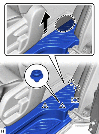
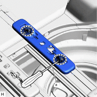
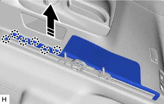
REMOVE REAR UPPER NO. 2 FLOOR BOARD PLATE
-
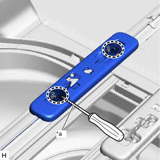
*a Protective Tape Lock Release Position Using a screwdriver, release the lock of the rear seat track slide stopper.
Tech Tips
Tape the screwdriver tip before use.
-
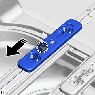
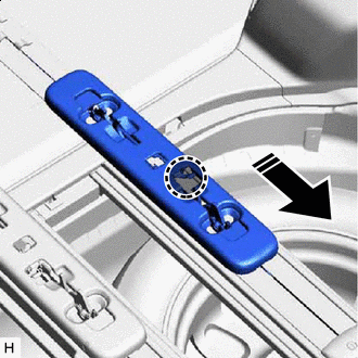
Press Position of the Rear Seat Track Slide Stopper Slide Direction Press the part of the rear seat track slide stopper shown in the illustration and slide the rear seat track slide stopper in the direction indicated by the arrow.
-
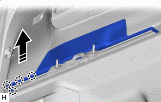
Place Hand Here Remove in this Direction Place your hand at the position shown in the illustration and pull in the direction indicated by the arrow to detach the claw, clip and guide.
-
Place Hand Here Remove in this Direction Place your hand at the position shown in the illustration and pull in the direction indicated by the arrow to detach the claw and guide and remove the rear upper No. 2 floor board plate.
-
-
REMOVE REAR UPPER NO. 1 FLOOR BOARD PLATE
-
*a Protective Tape Lock Release Position Using a screwdriver, release the lock of the rear seat track slide stopper.
Tech Tips
Tape the screwdriver tip before use.
-
Press Position of the Rear Seat Track Slide Stopper Slide Direction Press the part of the rear seat track slide stopper shown in the illustration and slide the rear seat track slide stopper in the direction indicated by the arrow.
-
Place Hand Here Remove in this Direction Place your hand at the position shown in the illustration and pull in the direction indicated by the arrow to detach the claw, clip and guide.
-
Place Hand Here Remove in this Direction Place your hand at the position shown in the illustration and pull in the direction indicated by the arrow to detach the claw and guide and remove the rear upper No. 1 floor board plate.
-
-
REMOVE DECK SIDE GARNISH LH
-
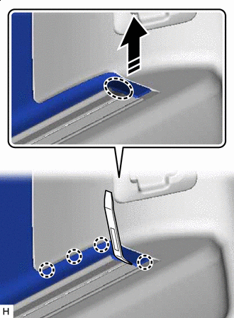
Insert Moulding Remover A Here Remove in this Direction Insert moulding remover A at the position shown in the illustration and pull in the direction indicated by the arrow to detach the claw.
-
Place Hand Here Remove in this Direction Order of Removal Place your hand in the gap created during the above procedure and pull in the direction indicated by the arrow to detach the claw as shown in the illustration.
-
Remove in this Direction Place your hand in the gap created during the above procedure and pull in the direction indicated by the arrows shown in the illustration to detach the claw and remove the deck side garnish LH.
-
-
REMOVE DECK SIDE GARNISH RH
-
Insert Moulding Remover A Here Remove in this Direction Insert moulding remover A at the position shown in the illustration and pull in the direction indicated by the arrow to detach the claw.
-
Place Hand Here Remove in this Direction Order of Removal Place your hand in the gap created during the above procedure and pull in the direction indicated by the arrow to detach the claw as shown in the illustration.
-
Remove in this Direction Place your hand in the gap created during the above procedure and pull in the direction indicated by the arrows shown in the illustration to detach the claw and remove the deck side garnish RH.
-
-
REMOVE NO. 2 LUGGAGE COMPARTMENT TRIM HOOK
-
Remove in this Direction (1) Remove in this Direction (2) Turn the end of the No. 2 luggage compartment trim hook 90° clockwise and pull in the direction indicated by the arrow shown in the illustration to remove the No. 2 luggage compartment trim hook.
-
-
REMOVE NO. 1 LUGGAGE COMPARTMENT TRIM HOOK
-
Remove in this Direction (1) Remove in this Direction (2) Turn the end of the No. 1 luggage compartment trim hook 90° clockwise and pull in the direction indicated by the arrow shown in the illustration to remove the No. 1 luggage compartment trim hook.
-
-
REMOVE ROPE HOOK ASSEMBLY
Tech Tips
Use the same procedure for both rope hook assemblies.
-
*a Protective Tape Using a screwdriver, detach the claw and open the cover.
Tech Tips
Tape the screwdriver tip before use.
-
Remove the bolt and rope hook assembly.
-
-
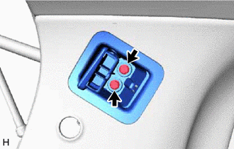
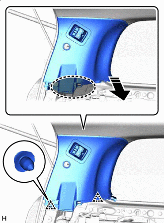
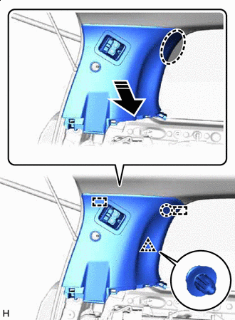
REMOVE REAR QUARTER TRIM PANEL ASSEMBLY LH
-
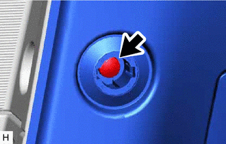
Remove the screw.
-
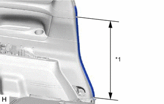
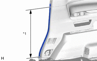
*1 No. 1 Slide Door Weatherstrip LH Disconnect the No. 1 slide door weatherstrip LH in the range shown in the illustration.
-
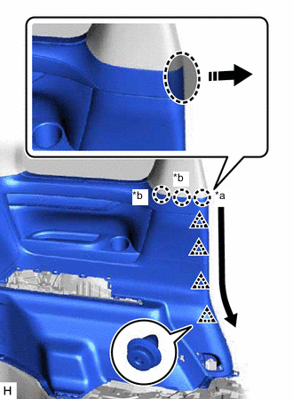
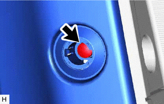
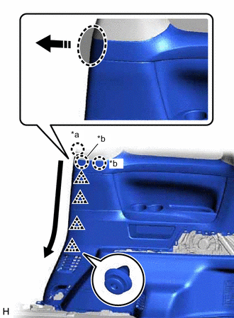
*a Claw A *b Claw B Place Hand Here Remove in this Direction Order of Removal Place your hand at the position shown in the illustration and pull in the direction indicated by the arrow to detach claw A.
-
Place your hand in the gap created during the above procedure and pull toward the vehicle interior to detach claw B and the clip in the direction indicated by the arrow shown in the illustration.
-
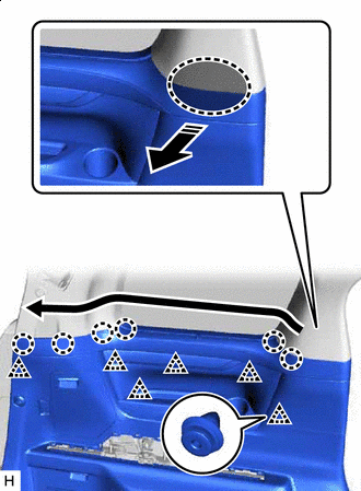
Place Hand Here Remove in this Direction Order of Removal Place your hand in the gap created during the above procedure and pull in the direction indicated by the arrow to detach the claw and clip as shown in the illustration.
-
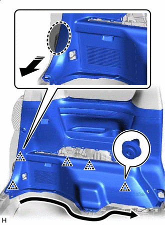
Place Hand Here Remove in this Direction Order of Removal Place your hand at the position shown in the illustration and pull in the direction indicated by the arrow to detach the clip in the direction indicated by the arrow.
-
Disconnect the connector and remove the rear quarter trim panel assembly LH.
-
-
REMOVE REAR QUARTER TRIM PANEL ASSEMBLY RH
-
Remove the screw.
-
*1 No. 1 Slide Door Weatherstrip RH Disconnect the No. 1 slide door weatherstrip RH in the range shown in the illustration.
-
*a Claw A *b Claw B Place Hand Here Remove in this Direction Order of Removal Place your hand at the position shown in the illustration and pull in the direction indicated by the arrow to detach claw A.
-
Place your hand in the gap created during the above procedure and pull toward the vehicle interior to detach claw B and the clip in the direction indicated by the arrow shown in the illustration.
-
Place Hand Here Remove in this Direction Order of Removal Place your hand in the gap created during the above procedure and pull in the direction indicated by the arrow to detach the claw and clip as shown in the illustration.
-
Place Hand Here Remove in this Direction Order of Removal Place your hand at the position shown in the illustration and pull in the direction indicated by the arrow to detach the clip in the direction indicated by the arrow.
-
Disconnect the connector and remove the rear quarter trim panel assembly RH.
-
-
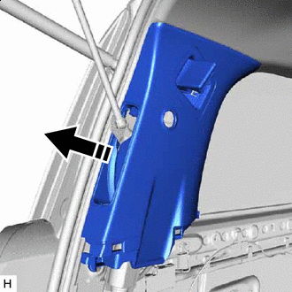
REMOVE QUARTER LOCK PILLAR GARNISH LH
-
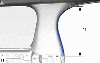
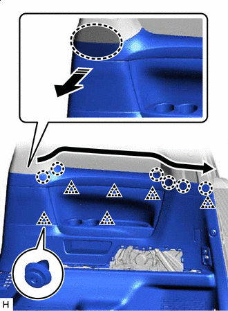
*1 No. 1 Slide Door Weatherstrip LH Disconnect the No. 1 slide door weatherstrip LH in the range shown in the illustration.
-
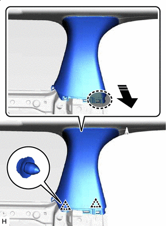
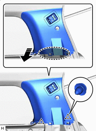
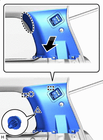
Place Hand Here Remove in this Direction Place your hand at the position shown in the illustration and pull in the direction indicated by the arrow to detach the clip.
-
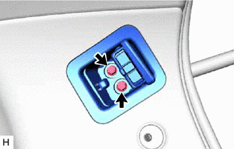
Place Hand Here Remove in this Direction Place your hands in the gaps shown in the illustration created during the above procedure and pull in the direction indicated by the arrow to detach the claw, clip and guide and remove the quarter lock pillar garnish LH.
-
-
REMOVE QUARTER LOCK PILLAR GARNISH RH
-
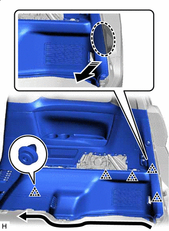
*1 No. 1 Slide Door Weatherstrip RH Disconnect the No. 1 slide door weatherstrip RH in the range shown in the illustration.
-
Place Hand Here Remove in this Direction Place your hand at the position shown in the illustration and pull in the direction indicated by the arrow to detach the clip.
-
Place Hand Here Remove in this Direction Place your hands in the gaps shown in the illustration created during the above procedure and pull in the direction indicated by the arrow to detach the claw, clip and guide and remove the quarter lock pillar garnish RH.
-
-
REMOVE CENTER BACK DOOR GARNISH (w/ Power Back Door)
-
REMOVE BACK DOOR SERVICE HOLE COVER LH (w/ Power Back Door)
-
REMOVE BACK DOOR SIDE GARNISH LH (w/ Power Back Door)
-
REMOVE INNER UPPER ROOF SIDE GARNISH LH
-
Cover Opening Direction Using moulding remover A, detach the claw and open the cover.
-
Remove the bolt and disconnect the rear No. 2 seat outer belt assembly LH.
-
Remove the 2 bolts.
-
Place Hand Here Remove in this Direction Place your hand at the position shown in the illustration and pull in the direction indicated by the arrow to detach the clip.
-
Place Hand Here Remove in this Direction Place your hands in the gaps shown in the illustration created during the above procedure and pull in the direction indicated by the arrow to detach the claw, clip and guide and remove the inner upper roof side garnish LH.
-
w/ Power Back Door:
-
Disconnect the power back door rod.
-
Remove in this Direction Remove the inner upper roof side garnish LH from the power back door rod.
-
-
-
REMOVE INNER UPPER ROOF SIDE GARNISH RH
-
Cover Opening Direction Using moulding remover A, detach the claw and open the cover.
-
Remove the bolt and disconnect the rear No. 2 seat outer belt assembly RH.
-
Remove the 2 bolts.
-
Place Hand Here Remove in this Direction Place your hand at the position shown in the illustration and pull in the direction indicated by the arrow to detach the clip.
-
Place Hand Here Remove in this Direction Place your hands in the gaps shown in the illustration created during the above procedure and pull in the direction indicated by the arrow to detach the claw, clip and guide and remove the inner upper roof side garnish RH.
-
-
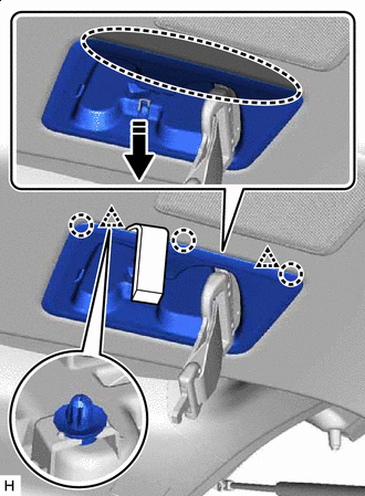
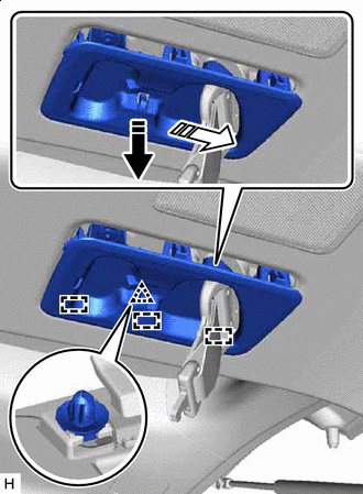
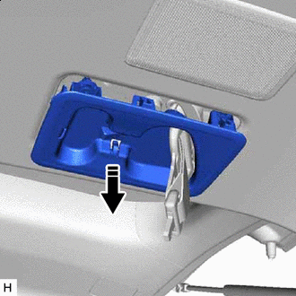
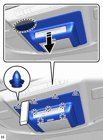
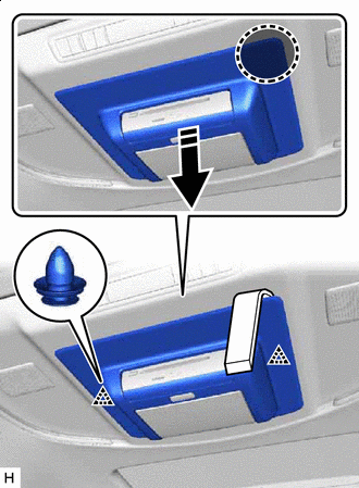
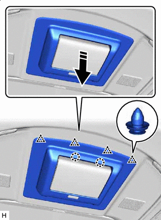
REMOVE MAP LIGHT ASSEMBLY
-
for LED Type:
-
for Bulb Type:
-
-
REMOVE VISOR BRACKET COVER LH
-
Open the visor assembly LH.
-
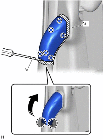
*a Protective Tape Insert Thin-bladed Screwdriver Here Insert a thin-bladed screwdriver at the position shown in the illustration and detach the claw and remove the visor bracket cover LH.
Tech Tips
Tape the thin-bladed screwdriver tip before use.
-
-
REMOVE VISOR BRACKET COVER RH
-
Open the visor assembly RH.
-
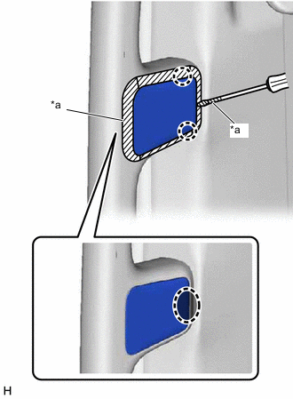
*a Protective Tape Insert Thin-bladed Screwdriver Here Insert a thin-bladed screwdriver at the position shown in the illustration and detach the claw and remove the visor bracket cover RH.
Tech Tips
Tape the thin-bladed screwdriver tip before use.
-
-
REMOVE VISOR ASSEMBLY LH
-
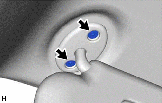
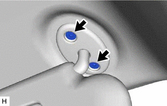
Remove the 2 screws.
-
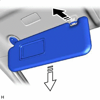
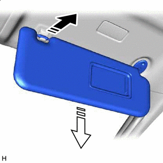
Remove in this Direction (1) Remove in this Direction (2) Pull in the direction indicated by the arrow shown in the illustration to disconnect the visor assembly LH from the visor holder.
-
Pull in the direction indicated by the arrow shown in the illustration to remove the visor assembly LH.
-
-
REMOVE VISOR ASSEMBLY RH
-
Remove the 2 screws.
-
Remove in this Direction (1) Remove in this Direction (2) Pull in the direction indicated by the arrow shown in the illustration to disconnect the visor assembly RH from the visor holder.
-
Pull in the direction indicated by the arrow shown in the illustration to remove the visor assembly RH.
-
-
REMOVE VISOR HOLDER
Tech Tips
Use the same procedure for both visor holders.
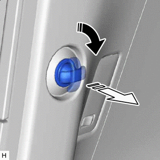
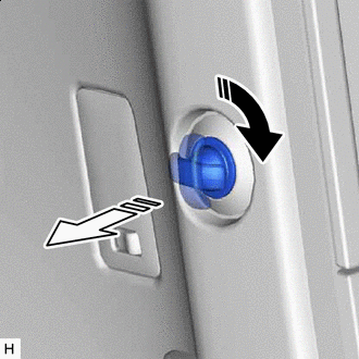
-
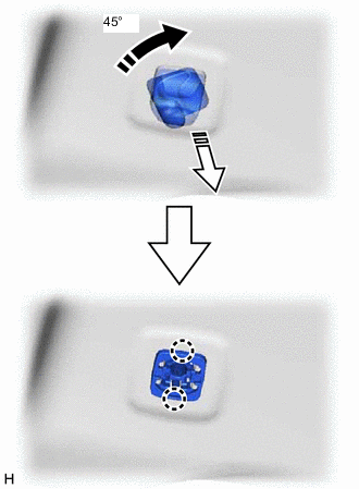
Remove in this Direction (1) Remove in this Direction (2) Turn the visor holder clockwise approximately 45° and pull it out as shown in the illustration.
-
Detach the claw and remove the visor holder.
-
-
REMOVE NO. 2 INNER REAR VIEW MIRROR STAY HOLDER COVER (w/ Digital Inner Mirror)
-
REMOVE INNER REAR VIEW MIRROR STAY HOLDER COVER (w/ Digital Inner Mirror)
-
REMOVE INNER REAR VIEW MIRROR STAY HOLDER COVER (w/ EC Mirror)
-
REMOVE RAIN SENSOR COVER (w/ Rain Sensor)
-
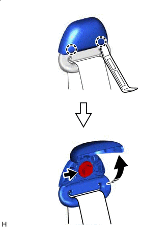
REMOVE ASSIST GRIP SUB-ASSEMBLY
Tech Tips
Use the same procedure for both assist grip sub-assemblies.
-
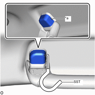
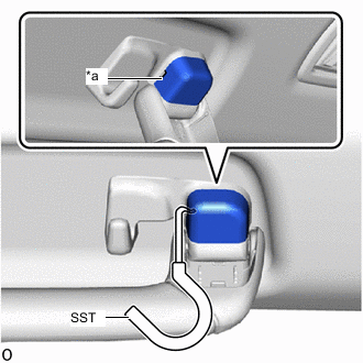
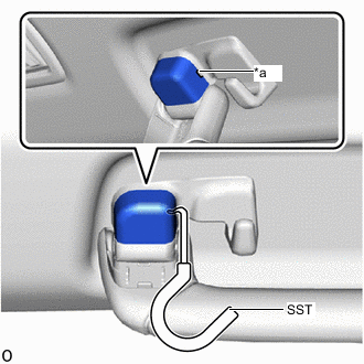
*a Cutout Insert SST into the cutout of the assist grip cover LH as shown in the illustration.
- SST
- 09813-00010
Note
To prevent the assist grip assembly from being damaged, make sure to insert SST straight into the cutout.
-
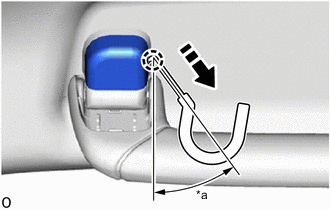
*a 30 to 45° Remove in this Direction Pull SST as shown in the illustration to disengage the claw.
Note
To prevent the assist grip assembly from being damaged, make sure to only pull SST as shown in the illustration.
Tech Tips
Use the same procedure for the claw on the other side of the assist grip cover LH.
-
Remove the assist grip cover LH.
Tech Tips
Use the same procedure for the LH side and RH side.
-
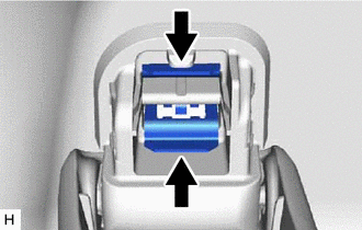
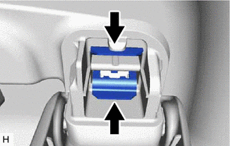
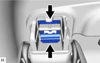
Pinch the clip with needle-nose pliers.
Tech Tips
Use the same procedure for both clips.
-
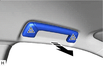
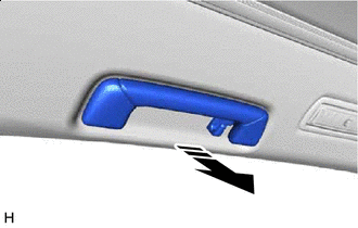
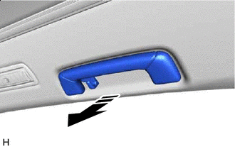
Remove in this Direction Hold the handle and pull in the direction indicated by the arrow shown in the illustration to remove the assist grip sub-assembly.
-
Using needle-nose pliers, remove the clip.
-
-
REMOVE REAR ASSIST GRIP ASSEMBLY LH
-
*a Cutout Insert SST into the cutout of the assist grip cover RH as shown in the illustration.
- SST
- 09813-00010
Note
To prevent the assist grip assembly from being damaged, make sure to insert SST straight into the cutout.
-
*a 30 to 45° Remove in this Direction Pull SST as shown in the illustration to disengage the claw.
Note
To prevent the assist grip assembly from being damaged, make sure to only pull SST as shown in the illustration.
Tech Tips
Use the same procedure for the claw on the other side of the assist grip cover RH.
-
Remove the assist grip cover RH.
Tech Tips
Use the same procedure for the LH side and RH side.
-
Pinch the clip with needle-nose pliers.
Tech Tips
Use the same procedure for both clips.
-
Remove in this Direction Hold the handle and pull in the direction indicated by the arrow shown in the illustration to remove the rear assist grip assembly LH.
-
Using needle-nose pliers, remove the clip.
-
-
REMOVE REAR ASSIST GRIP ASSEMBLY RH
-
*a Cutout Insert SST into the cutout of the assist grip cover LH as shown in the illustration.
- SST
- 09813-00010
Note
To prevent the assist grip assembly from being damaged, make sure to insert SST straight into the cutout.
-
*a 30 to 45° Remove in this Direction Pull SST as shown in the illustration to disengage the claw.
Note
To prevent the assist grip assembly from being damaged, make sure to only pull SST as shown in the illustration.
Tech Tips
Use the same procedure for the claw on the other side of the assist grip cover LH.
-
Remove the assist grip cover LH.
Tech Tips
Use the same procedure for the LH side and RH side.
-
Pinch the clip with needle-nose pliers.
Tech Tips
Use the same procedure for both clips.
-
Remove in this Direction Hold the handle and pull in the direction indicated by the arrow shown in the illustration to remove the rear assist grip assembly RH.
-
Using needle-nose pliers, remove the clip.
-
-
REMOVE INTEGRATION CONTROL AND PANEL ASSEMBLY
-
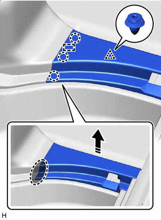
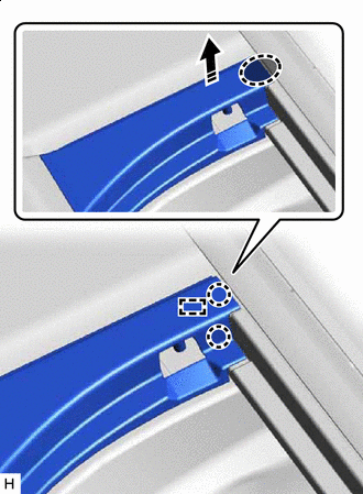
REMOVE SEAT BELT ANCHOR COVER
-
Insert Moulding Remover D Here Remove in this Direction Insert moulding remover D at the position shown in the illustration and pull in the direction indicated by the arrow to detach the claw and clip.
-
Remove in this Direction (1) Remove in this Direction (2) Place your hand in the gap created during the above procedure and pull in the direction indicated by the arrows shown in the illustration to detach the clip and guide.
-
Remove in this Direction Pass the rear No. 2 seat 3 point type belt assembly through the seat belt anchor cover, and then remove the seat belt anchor cover.
-
-
REMOVE COOLER PLATE
-
REMOVE NO. 1 COOLER AIR DUCT
-
REMOVE FRONT ROOF SIDE RAIL GARNISH LH
-
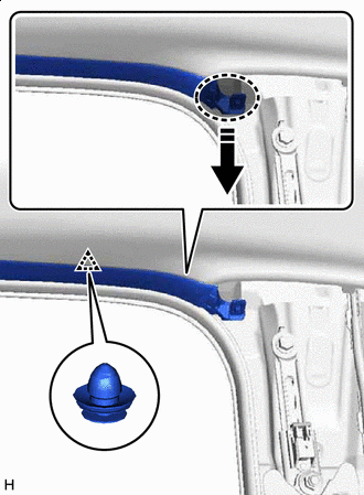
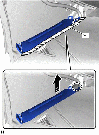
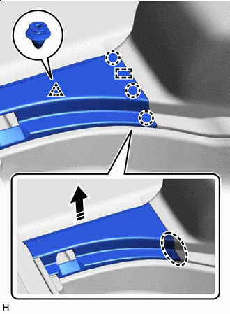
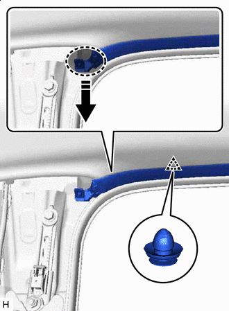
Place Hand Here Remove in this Direction Place your hand at the position shown in the illustration and pull in the direction indicated by the arrow to detach the clip.
-
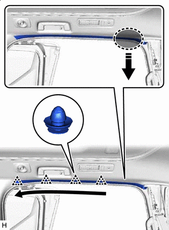
Place Hand Here Remove in this Direction Order of Removal Place your hand in the gap shown in the illustration created during the above procedure and pull in the direction indicated by the arrow to detach the clip in the direction indicated by the arrow and remove the front roof side rail garnish LH.
-
-
REMOVE FRONT ROOF SIDE RAIL GARNISH RH
-
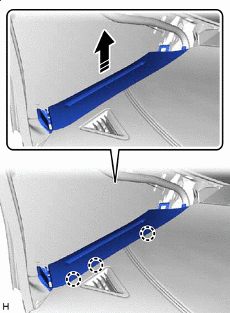
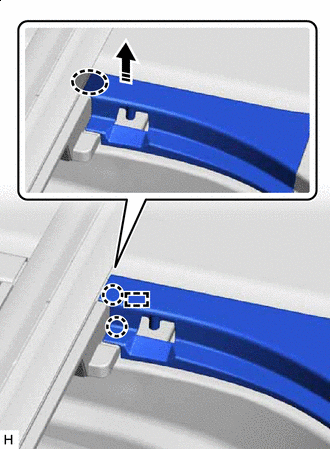
Place Hand Here Remove in this Direction Place your hand at the position shown in the illustration and pull in the direction indicated by the arrow to detach the clip.
-
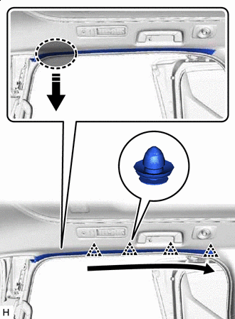
Place Hand Here Remove in this Direction Order of Removal Place your hand in the gap shown in the illustration created during the above procedure and pull in the direction indicated by the arrow to detach the clip in the direction indicated by the arrow and remove the front roof side rail garnish RH.
-
-
REMOVE REAR ROOF SIDE RAIL GARNISH LH
-
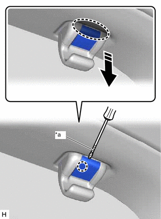
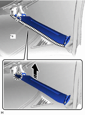
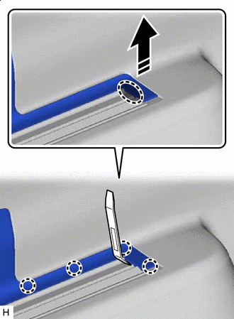
*a Protective Tape Insert Thin-bladed Screwdriver Here Sunshade Hook Pulling Direction w/ Sunshade:
-
Insert a thin-bladed screwdriver and pull the sunshade hook in the direction indicated by the arrow shown in the illustration to detach the claw.
Tech Tips
-
Use the same procedure for both sunshade hooks.
-
Tape the thin-bladed screwdriver tip before use.
-
-
-
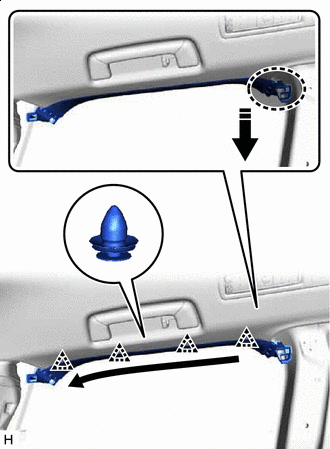
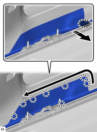
Place Hand Here Remove in this Direction Order of Removal Place your hand at the position shown in the illustration and pull in the direction indicated by the arrow to detach the clip in the direction indicated by the arrow and remove the rear roof side rail garnish LH.
-
-
REMOVE REAR ROOF SIDE RAIL GARNISH RH
-
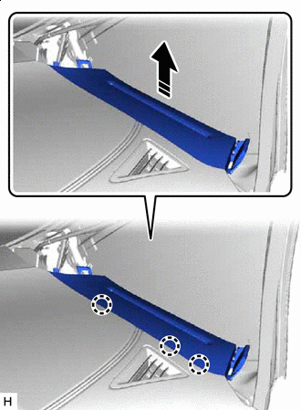
*a Protective Tape Insert Thin-bladed Screwdriver Here Sunshade Hook Pulling Direction w/ Sunshade:
-
Insert a thin-bladed screwdriver and pull the sunshade hook in the direction indicated by the arrow shown in the illustration to detach the claw.
Tech Tips
-
Use the same procedure for both sunshade hooks.
-
Tape the thin-bladed screwdriver tip before use.
-
-
-
Place Hand Here Remove in this Direction Order of Removal Place your hand at the position shown in the illustration and pull in the direction indicated by the arrow to detach the clip in the direction indicated by the arrow and remove the rear roof side rail garnish RH.
-
-
REMOVE TELEVISION BASE (w/ Rear Entertainment System)
-
for 12 Inch:
-
Insert Moulding Remover D Here Remove in this Direction Insert moulding remover D at the position shown in the illustration and pull in the direction indicated by the arrow to detach the claw, clip and guide.
-
Insert Moulding Remover D Here Remove in this Direction Insert moulding remover D at the position shown in the illustration and pull in the direction indicated by the arrow to detach the claw, clip and guide and remove the television base.
-
-
for 8 Inch:
-
Insert Moulding Remover D Here Remove in this Direction Insert moulding remover D at the position shown in the illustration and pull in the direction indicated by the arrow to detach the claw and clip.
-
Insert Moulding Remover D Here Remove in this Direction Insert moulding remover D at the positions shown in the illustration and pull in the direction indicated by the arrow to detach the clip.
-
Remove in this Direction Place your hand in the gap created during the previous procedure and pull in the direction indicated by the arrow shown in the illustration to remove the television base.
-
-
-
REMOVE FRONT ROOF HEADLINING TRIM SUB-ASSEMBLY (for Normal Roof)
-
w/o Digital Inner Mirror:
-
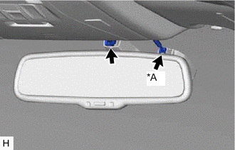
*A w/ Rain Sensor Disconnect the connector.
-
-
w/ Digital Inner Mirror:
-
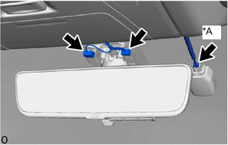
*A w/ Rain Sensor Disconnect the connector.
-
-
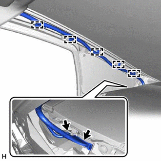
Disconnect the connector and detach the clamp from the front pillar LH.
-
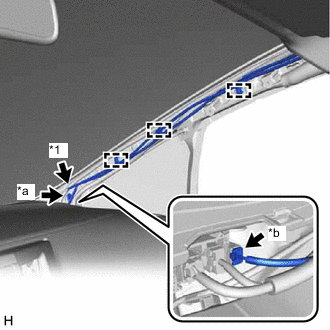
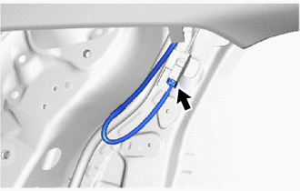
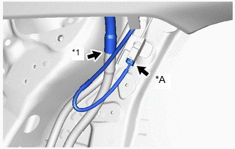
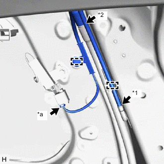
*1 Washer Hose *a Bolt *b Connector Remove the bolt.
-
Disconnect the connector and washer hose and detach the clamp from the front pillar RH.
-
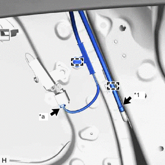
*1 Washer Hose *a Connector Disconnect the connector and washer hose and detach the clamp from the rear pillar RH.
-
w/ Digital Inner Mirror:
-
Disconnect the connector.
-
-
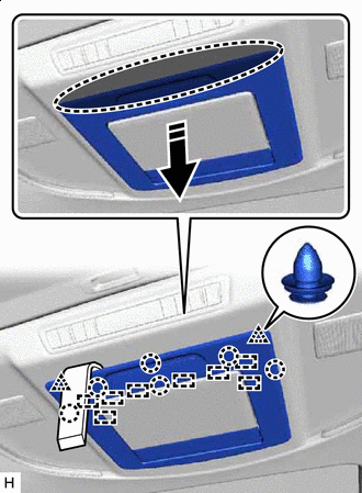
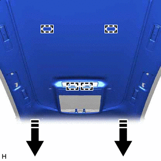
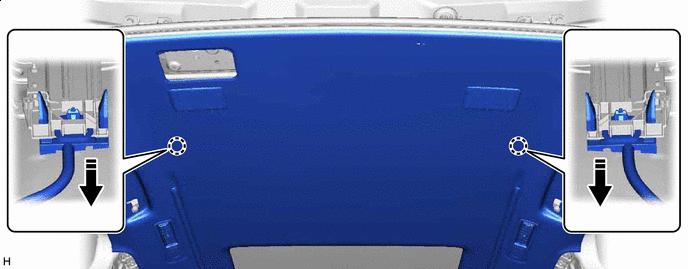
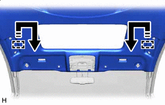
Place your hands on the rear end of the front roof headlining sub-assembly and pull as shown in the illustration to detach the clip.
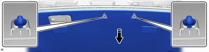
Remove in this Direction - - -
Place your hand in the gap created during the above procedure and move the front roof headlining trim sub-assembly in the direction indicated by the arrow shown in the illustration to detach the guide.
Remove in this Direction - - -
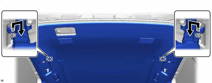
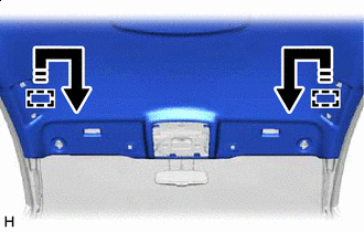
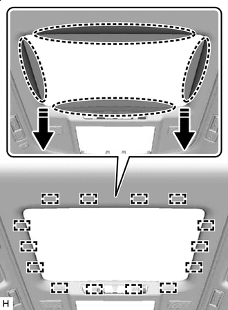
Remove in this Direction w/o Rear Entertainment System:
Place your hands on the left and right sides of the front roof headlining trim sub-assembly and pull in the direction indicated by the arrow shown in the illustration to detach the fasteners.
-
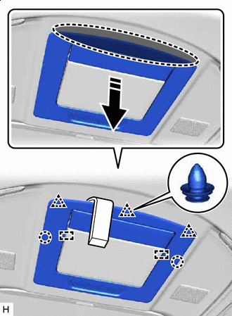
Remove in this Direction w/ Rear Entertainment System:
Place your hands on the left and right sides of the front roof headlining trim sub-assembly and pull in the direction indicated by the arrow shown in the illustration to detach the fasteners.
-
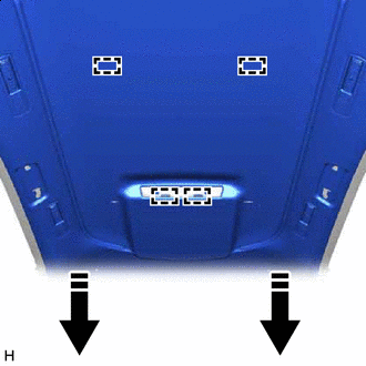
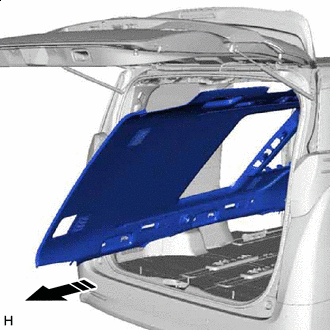
Remove in this Direction Place your hands on the left and right sides of the front roof headlining trim sub-assembly and move the front roof headlining trim sub-assembly in the direction indicated by the arrow shown in the illustration to detach the guide.
-
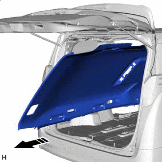
Remove in this Direction Turn the front roof headlining trim sub-assembly diagonally and bend slightly to remove it from the back door.
Note
-
Make sure wrinkles do not form in the front roof headlining trim sub-assembly during removal.
-
Make sure that the front roof headlining trim sub-assembly does not get caught on anything as it may become bent or damaged.
-
Do not damage the front roof headlining trim sub-assembly or vehicle interior.
-
-
-
REMOVE FRONT ROOF HEADLINING TRIM SUB-ASSEMBLY (for Sliding Roof)
-
w/o Digital Inner Mirror:
-
*A w/ Rain Sensor Disconnect the connector.
-
-
w/ Digital Inner Mirror:
-
*A w/ Rain Sensor Disconnect the connector.
-
-
Disconnect the connector and detach the clamp from the front pillar LH.
-
*1 Washer Hose *a Bolt *b Connector Remove the bolt.
-
Disconnect the connector and washer hose and detach the clamp from the front pillar RH.
-
*A w/ Digital Inner Mirror *1 Rear Sliding Roof Drain Hose LH Disconnect the rear sliding roof drain hose LH.
-
w/ Digital Inner Mirror:
-
Disconnect the connector.
-
-
*1 Washer Hose *2 Rear Sliding Roof Drain Hose RH *a Connector Disconnect the connector, washer hose and rear sliding roof drain hose RH and detach the clamp from the rear pillar RH.
-
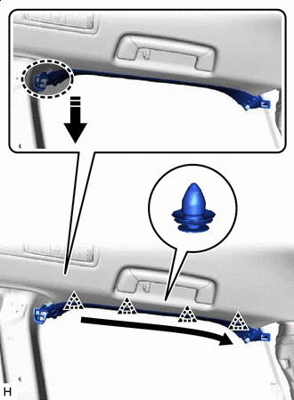
Place your hands on the rear end of the front roof headlining sub-assembly and pull as shown in the illustration to detach the clip.
Remove in this Direction - - -
Place your hand in the gap created during the above procedure and pull in the direction indicated by the arrows shown in the illustration to detach the claw.
Remove in this Direction - - -
Place Hand Here Remove in this Direction Place your hand in the gap on the interior of the sliding roof and pull in the direction indicated by the arrow shown in the illustration to detach the fasteners.
-
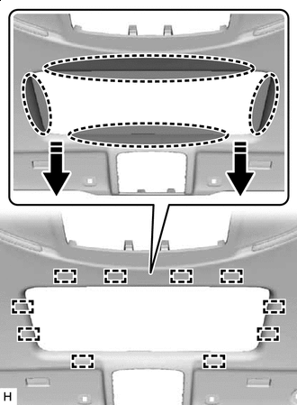
Place Hand Here Remove in this Direction Place your hand in the gap on the interior of the sliding roof and pull in the direction indicated by the arrow shown in the illustration to detach the fasteners.
-
Remove in this Direction Place your hands on the left and right sides of the front roof headlining trim sub-assembly and move the front roof headlining trim sub-assembly in the direction indicated by the arrow shown in the illustration to detach the guide.
-
Remove in this Direction Turn the front roof headlining trim sub-assembly diagonally and bend slightly to remove it from the back door.
Note
-
Make sure wrinkles do not form in the front roof headlining trim sub-assembly during removal.
-
Make sure that the front roof headlining trim sub-assembly does not get caught on anything as it may become bent or damaged.
-
Do not damage the front roof headlining trim sub-assembly or vehicle interior.
-
-