INSTRUMENT PANEL SAFETY PAD(for RHD) INSTALLATION
CAUTION / NOTICE / HINT
PROCEDURE
-
INSTALL INSTRUMENT PANEL SAFETY PAD ASSEMBLY
-


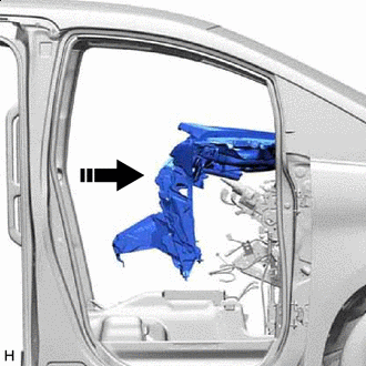
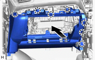
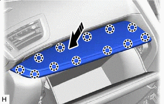
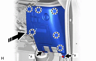
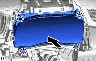
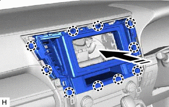
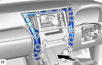
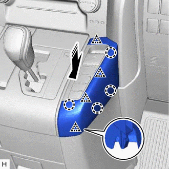
Movement Direction Insert the instrument panel safety pad assembly into the vehicle from the slide door opening.
Note
-
Make sure that the instrument panel safety pad assembly does not get caught on anything as it may become bent or damaged.
-
Do not damage the instrument panel safety pad assembly or vehicle interior.
-
-
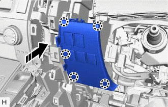
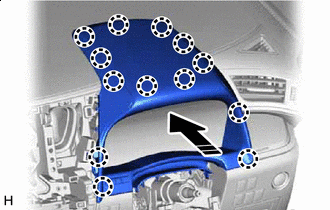
Movement Direction Set the instrument panel safety pad assembly on the instrument panel reinforcement assembly.
-
w/o Navigation System:
-
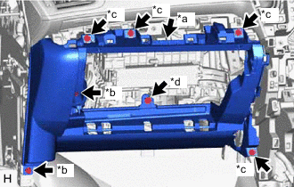
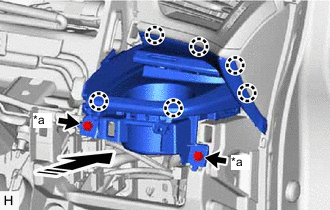
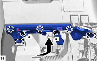
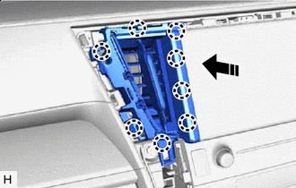
Attach the guide to install the instrument panel safety pad assembly.
-
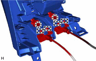
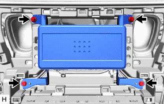
Install the 2 passenger airbag installation bolts <H>.
- Torque:
- 20 N*m { 204 kgf*cm, 15 ft.*lbf }
-
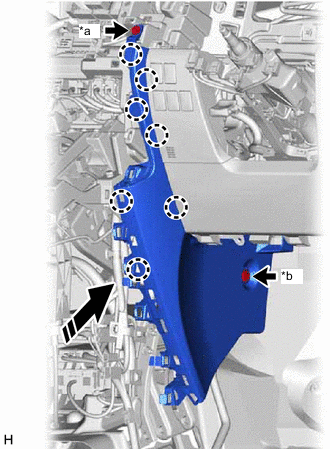
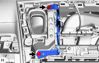
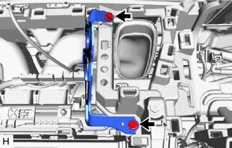
Install the 8 bolts <A>, 2 clips <F> and 4 nuts <G>.
-
Connect the connector and attach the clamp.
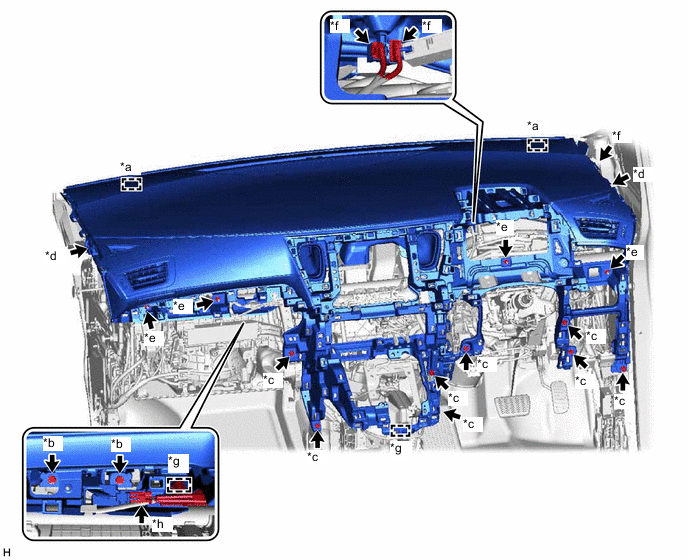
*a Guide *b Passenger Airbag Installation Bolt <H> *c Bolt <A> *d Clip <F> *e Nut <G> *f Connector *g Clamp *h Passenger Airbag Connector -
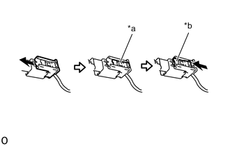
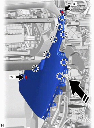
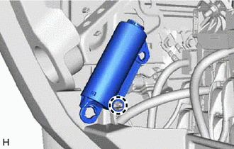
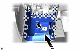
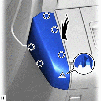
*a Lock Slider *b Lock Position Connect the passenger airbag connector.
Note
When handling the passenger airbag connector, take care not to damage the airbag wire harness.
-
Check that the lock slider is in the lock position.
-
-
w/ Navigation System:
-
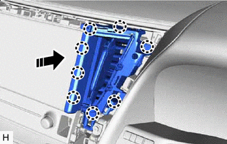
Attach the guide to install the instrument panel safety pad assembly.
-
Install the 2 passenger airbag installation bolts <H>.
- Torque:
- 20 N*m { 204 kgf*cm, 15 ft.*lbf }
-
Install the 8 bolts <A>, 2 clips <F> and 4 nuts <G>.
-
Connect the connector and attach the clamp.
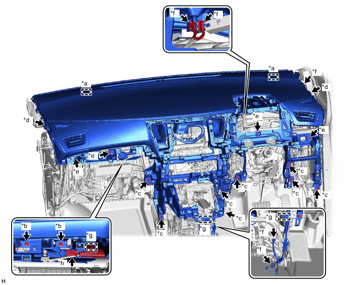
*a Guide *b Passenger Airbag Installation Bolt <H> *c Bolt <A> *d Clip <F> *e Nut <G> *f Connector *g Clamp *h Passenger Airbag Connector -
*a Lock Slider *b Lock Position Connect the passenger airbag connector.
Note
When handling the passenger airbag connector, take care not to damage the airbag wire harness.
-
Check that the lock slider is in the lock position.
-
-
-
INSTALL SHIFT LEVER ASSEMBLY
-
CONNECT TRANSMISSION CONTROL CABLE ASSEMBLY
-
INSTALL LOWER FRONT PILLAR GARNISH LH
-
INSTALL LOWER FRONT PILLAR GARNISH RH
-
INSTALL FRONT PILLAR GARNISH LH
-
INSTALL FRONT PILLAR GARNISH RH
-
INSTALL PILLAR ASSIST GRIP ASSEMBLY
-
INSTALL ASSIST GRIP PLUG
-
INSTALL LOWER INSTRUMENT PANEL
-
Install in this Direction Attach the claw to install the lower instrument panel as shown in the illustration.
-
*a Connector *b Bolt <A> *c Screw <C> *d Screw <D> Connect the connector.
-
Install the 2 bolts <A>, 4 screws <C> and screw <D>.
-
-
INSTALL LOWER NO. 2 INSTRUMENT PANEL FINISH PANEL
-
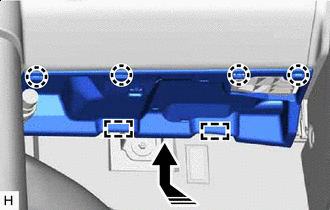
*a Screw <C> *b Clip <E> Install in this Direction Attach the claw to install the lower No. 2 instrument panel finish panel as shown in the illustration.
-
Install the screw <C> and clip <E>.
-
-
INSTALL NO. 2 INSTRUMENT PANEL UNDER COVER SUB-ASSEMBLY
-
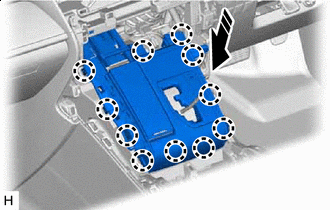
Install in this Direction Connect the connector.
-
Attach the guide and claw to install the No. 2 instrument panel under cover sub-assembly as shown in the illustration.
-
-
INSTALL COWL SIDE TRIM BOARD LH
-
INSTALL NO. 3 INSTRUMENT CLUSTER FINISH PANEL GARNISH
-

Install in this Direction for VIP Captain Seat:
-
Attach the claw to install the No. 3 instrument cluster finish panel garnish as shown in the illustration.
-
-
Install in this Direction except VIP Captain Seat:
-
Attach the claw to install the No. 3 instrument cluster finish panel garnish as shown in the illustration.
-
-
-
INSTALL GLOVE COMPARTMENT DOOR STOPPER SUB-ASSEMBLY
-
Attach the claw to install the glove compartment door stopper sub-assembly.
-
-
INSTALL GLOVE COMPARTMENT DOOR ASSEMBLY
-
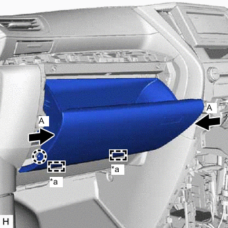
*a Hinge Attach the hinge.
-
Press the parts labeled A in the illustration in the direction indicated by the arrows and attach the stoppers to install the glove compartment door assembly.
-
Attach the claw to connect the glove compartment door stopper sub-assembly.
-
-
INSTALL INSTRUMENT PANEL CUP HOLDER
-
*a Screw <B> Install in this Direction Attach the claw to install the instrument panel cup holder as shown in the illustration.
-
Install the 2 screws <B>.
-
-
INSTALL LOWER INSTRUMENT PANEL FINISH PANEL ASSEMBLY
-
Attach the guide and claw to connect the hood lock control lever sub-assembly and fuel lid lock open lever to the lower instrument panel finish panel assembly.
-
Connect the connector.
-
*a Bolt <A> Install in this Direction Attach the claw to install the lower instrument panel finish panel assembly as shown in the illustration.
-
Install the 2 bolts <A>.
-
-
INSTALL NO. 1 SWITCH HOLE BASE
-
Install in this Direction Connect the connector.
-
Attach the claw to install the No. 1 switch hole base as shown in the illustration.
-
-
INSTALL LOWER NO. 1 INSTRUMENT PANEL AIRBAG ASSEMBLY
-
INSTALL LOWER NO. 1 INSTRUMENT PANEL FINISH PANEL
-
*a Screw <C> *b Clip <E> Install in this Direction Attach the claw to install the lower No. 1 instrument panel finish panel as shown in the illustration.
-
Install the screw <C> and clip <E>.
-
-
INSTALL NO. 1 INSTRUMENT PANEL UNDER COVER SUB-ASSEMBLY
-
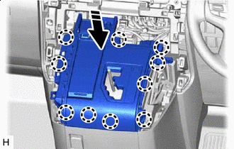
*a Screw <B> Install in this Direction Connect the connector and attach the clamp.
-
Attach the guide and claw to install the No. 1 instrument panel under cover sub-assembly as shown in the illustration.
-
Install the 2 screws <B>.
-
-
INSTALL COWL SIDE TRIM BOARD RH
-
INSTALL COMBINATION METER ASSEMBLY
-
Install in this Direction Connect the connector and attach the clamp.
-
Attach the claw to install the combination meter assembly as shown in the illustration.
-
-
INSTALL INSTRUMENT PANEL FINISH PANEL ASSEMBLY
-
Install in this Direction Connect the connector.
-
Attach the claw to install the instrument panel finish panel assembly as shown in the illustration.
-
-
INSTALL INSTRUMENT CLUSTER FINISH PANEL ASSEMBLY (for Separate Console Box Type)
-
*a Bolt <A> Install in this Direction Connect the connector.
-
Attach the claw to install the instrument cluster finish panel assembly as shown in the illustration.
-
Install the bolt <A>.
-
-
INSTALL INSTRUMENT PANEL BOX ASSEMBLY (for Separate Console Box Type)
-
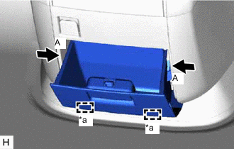
*a Hinge Attach the hinge.
-
Press the parts labeled A in the illustration in the direction indicated by the arrows and attach the stoppers to install the instrument panel box assembly.
-
-
INSTALL LOWER CENTER INSTRUMENT CLUSTER FINISH PANEL SUB-ASSEMBLY
-
for Integrated Console Box Type:
-
Install in this Direction Connect the connector.
-
Attach the claw to install the lower center instrument cluster finish panel sub-assembly as shown in the illustration.
-
-
for Separate Console Box Type:
-
Install in this Direction Connect the connector.
-
Attach the claw to install the lower center instrument cluster finish panel sub-assembly as shown in the illustration.
-
-
-
INSTALL COMBINATION SWITCH ASSEMBLY
-
INSTALL SHIFT LEVER KNOB SUB-ASSEMBLY
-
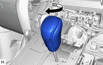
Install in this Direction Install the shift lever knob sub-assembly and twist it in the direction indicated by the arrow.
-
-
INSTALL AIR CONDITIONING CONTROL ASSEMBLY
-
INSTALL RADIO TUNER OPENING COVER (w/o Navigation System, w/ Cover)
-
Install the radio tuner opening cover with the 4 screws.
-
-
INSTALL NO. 2 RADIO BRACKET (w/o Navigation System, w/o Cover)
-
Install the No. 2 radio bracket with the 2 screws.
-
-
INSTALL NO. 1 RADIO BRACKET (w/o Navigation System, w/o Cover)
-
Install the No. 1 radio bracket with the 2 screws.
-
-
INSTALL NAVIGATION RECEIVER ASSEMBLY (w/ Navigation System)
-
INSTALL CENTER INSTRUMENT CLUSTER FINISH PANEL SUB-ASSEMBLY (w/o Navigation System)
-
Install in this Direction Connect the connector.
-
Attach the claw to install the center instrument cluster finish panel sub-assembly as shown in the illustration.
-
-
INSTALL NO. 4 INSTRUMENT PANEL REGISTER ASSEMBLY (w/ Navigation System)
-
Install in this Direction Attach the claw to install the No. 4 instrument panel register assembly as shown in the illustration.
-
-
INSTALL NO. 3 INSTRUMENT PANEL REGISTER ASSEMBLY (w/ Navigation System)
-
Install in this Direction Attach the claw to install the No. 3 instrument panel register assembly as shown in the illustration.
-
-
INSTALL UPPER INSTRUMENT PANEL FINISH PANEL
-
Install in this Direction Attach the claw to install the upper instrument panel finish panel as shown in the illustration.
-
-
INSTALL CENTER NO. 2 INSTRUMENT CLUSTER FINISH PANEL (for Separate Console Box Type)
-
Install in this Direction Attach the claw and clip to install the center No. 2 instrument cluster finish panel as shown in the illustration.
-
-
INSTALL CENTER NO. 1 INSTRUMENT CLUSTER FINISH PANEL (for Separate Console Box Type)
-
Install in this Direction Attach the claw and clip to install the center No. 1 instrument cluster finish panel as shown in the illustration.
-
-
INSTALL HEADLIGHT DIMMER SWITCH ASSEMBLY
-
INSTALL CONSOLE BOX ASSEMBLY (for Integrated Console Box Type)
-
INSTALL REAR NO. 1 SEAT ASSEMBLY LH
-
for Power Captain Seat without Memory:
-
for Power Captain Seat with Memory:
-
for Manual Captain Seat:
-
-
INSTALL REAR NO. 1 SEAT ASSEMBLY RH
-
for Power Captain Seat without Memory:
-
for Power Captain Seat with Memory:
-
for Manual Captain Seat:
-
-
INSTALL FRONT SEAT ASSEMBLY LH
-
for Manual Seat:
-
for Power Seat:
-
-
INSTALL FRONT SEAT ASSEMBLY RH
-
for Manual Seat:
-
for Power Seat:
-
-
CONNECT CABLE TO NEGATIVE BATTERY TERMINAL
Note
When disconnecting the cable, some systems need to be initialized after the cable is reconnected.
-
CHECK SRS WARNING LIGHT