INSTRUMENT PANEL SAFETY PAD(for RHD) REASSEMBLY
PROCEDURE
-
INSTALL LOWER INSTRUMENT SIDE PATCH
Tech Tips
Use the same procedure for both lower instrument side patches.
-
Attach the claw to install the lower instrument side patch.
-
-
INSTALL GLOVE COMPARTMENT DOOR CHECK CUSHION
Tech Tips
Use the same procedure for both glove compartment door check cushions.
-
Attach the claw to install the glove compartment door check cushion.
-
-
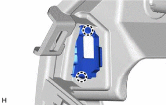
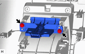
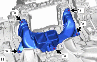
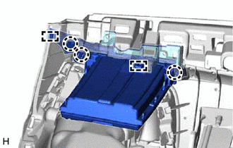
INSTALL INSTRUMENT PANEL COIN BOX SUB-ASSEMBLY
-
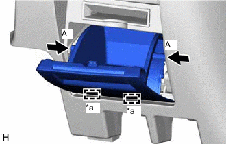
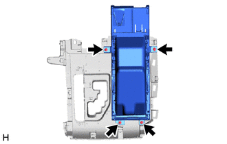
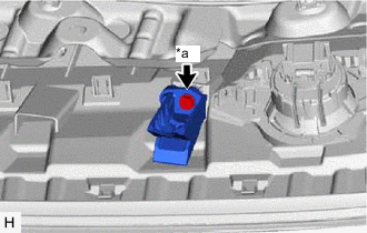
*a Hinge Attach the hinge.
-
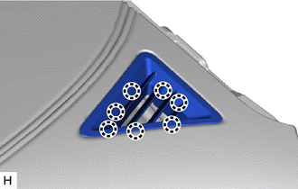
Press the parts labeled A in the illustration in the direction indicated by the arrows and attach the stoppers to install the instrument panel coin box sub-assembly.
-
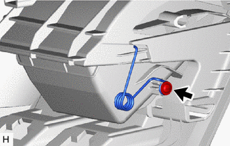
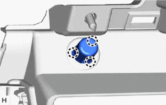
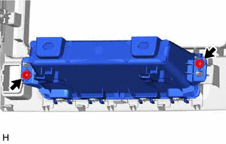
Install the spring with the screw.
-
-
INSTALL INSTRUMENT PANEL HOLE COVER
-
Install the instrument panel hole cover with the 2 screws.
-
-
INSTALL INSTRUMENT PANEL EXTENSION
-
Attach the claw to install the instrument panel extension.
-
Install the 2 screws.
-
-
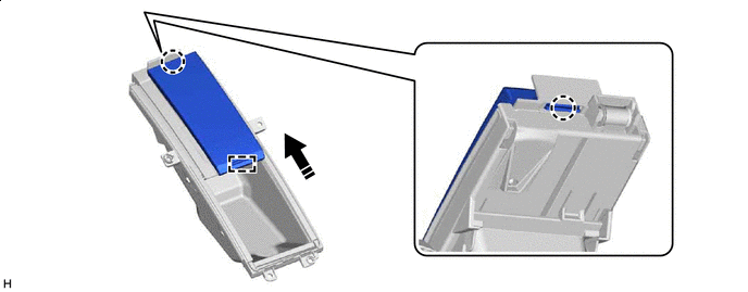
INSTALL LOWER INSTRUMENT CLUSTER FINISH PANEL
-
Attach the claw to install the lower instrument cluster finish panel.
-
-
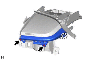
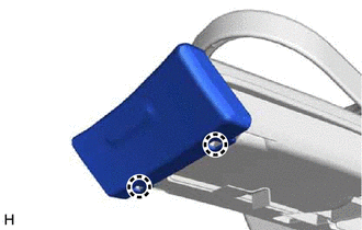
INSTALL INSTRUMENT CLUSTER FINISH PANEL GARNISH ASSEMBLY
-
Fully open the lid of the center instrument panel box sub-assembly as shown in the illustration.
-
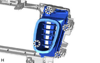
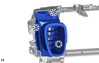
Attach the claw and guide to install the instrument cluster finish panel garnish assembly.

Opening Direction - -
-
-
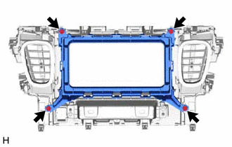
INSTALL CENTER INSTRUMENT PANEL BOX SUB-ASSEMBLY
-
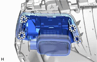
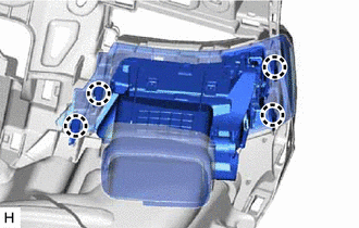
Install the center instrument panel box sub-assembly with the 4 screws.
-
-
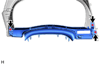
INSTALL CENTER INSTRUMENT PANEL BOX (w/o Navigation System)
-
Install the center instrument panel box with the 2 screws.
-
-
INSTALL NO. 4 INSTRUMENT PANEL REGISTER ASSEMBLY (w/o Navigation System)
-
Attach the claw to install the No. 4 instrument panel register assembly.
-
-
INSTALL NO. 3 INSTRUMENT PANEL REGISTER ASSEMBLY (w/o Navigation System)
-
Attach the claw to install the No. 3 instrument panel register assembly.
-
-
INSTALL INSTRUMENT CLUSTER FINISH PANEL END (w/o Navigation System)
-
Install the instrument cluster finish panel end with the 4 screws.
-
-
INSTALL INSTRUMENT CLUSTER FINISH PANEL SUB-ASSEMBLY
-
Install the instrument cluster finish panel sub-assembly with the 3 screws.
-
-
INSTALL ANTENNA CORD SUB-ASSEMBLY (w/ Navigation System)
-
INSTALL NAVIGATION ANTENNA ASSEMBLY (w/ Navigation System)
-
INSTALL NO. 1 HEATER TO REGISTER DUCT
*a Screw <B>
-
Install the No. 1 heater to register duct with the 5 screws <B>.
-
-
INSTALL AIR DUCT SUB-ASSEMBLY
-
INSTALL NO. 1 ION GENERATOR SUB-ASSEMBLY
-
INSTALL INSTRUMENT PANEL PASSENGER WITHOUT DOOR AIRBAG ASSEMBLY
-
INSTALL NO. 2 INSTRUMENT PANEL WIRE
-
INSTALL SIDE DEFROSTER NOZZLE LH
-
Attach the claw to install the side defroster nozzle LH.
-
-
INSTALL SIDE DEFROSTER NOZZLE RH
-
Attach the claw to install the side defroster nozzle RH.
-
-
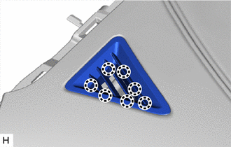
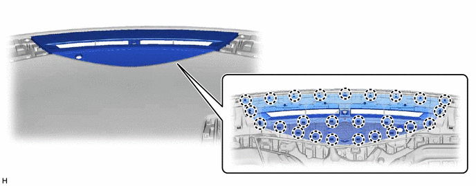
INSTALL INSTRUMENT PANEL CUSHION
Note
Installing the part with double-sided tape residue still remaining can cause poor adhesion. Therefore, using a cloth or other material, clean the part until the residue is completely removed (when reusing the instrument panel safety pad assembly).
-
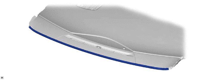
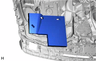
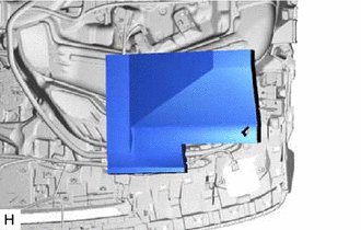
Remove the peeling paper from a new instrument panel cushion and press firmly to install the instrument panel cushion in the position shown in the illustration.
-
-
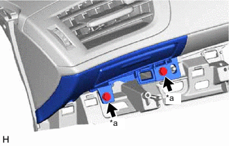
INSTALL NO. 1 INSTRUMENT PANEL PIN
Tech Tips
Use the same procedure for both No. 1 instrument panel pins.
-
*a Screw <B> Install the No. 1 instrument panel pin with the screw <B>.
-
-
INSTALL NO. 2 INSTRUMENT PANEL WIRE
-
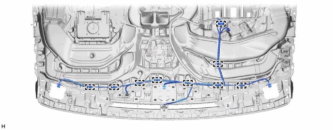
Attach the clamp to install the No. 2 instrument panel wire.
-
Install the passenger side cushion.
-
Install the driver side cushion.
-
-
INSTALL NO. 2 INSTRUMENT PANEL REGISTER ASSEMBLY
-
Attach the claw to install the No. 2 instrument panel register assembly.
-
-
INSTALL NO. 1 INSTRUMENT PANEL REGISTER ASSEMBLY
-
Attach the claw to install the No. 1 instrument panel register assembly.
-
-
INSTALL NO. 2 INSTRUMENT PANEL CUP HOLDER
-
Attach the claw and guide to install the No. 2 instrument panel cup holder.
-
*a Screw <B> Install the 2 screws <B>.
-
-
INSTALL FRONT NO. 3 SPEAKER ASSEMBLY (w/ Front Center Speaker)
-
INSTALL FRONT NO. 2 SPEAKER ASSEMBLY
Tech Tips
Use the same procedure for both front No. 2 speaker assemblies.
Note
Do not touch the cone part of the front No. 2 speaker assembly.
-
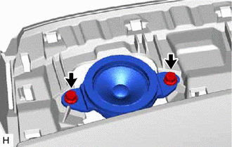
Connect the connector.
-
Install the front No. 2 speaker assembly with the 2 screws.
-
-
INSTALL NO. 1 DEFROSTER NOZZLE GARNISH
-
Attach the claw to install the No. 1 defroster nozzle garnish.
-
-
INSTALL AUTOMATIC LIGHT CONTROL SENSOR
-
INSTALL NO. 2 INSTRUMENT PANEL SPEAKER PANEL SUB-ASSEMBLY
-
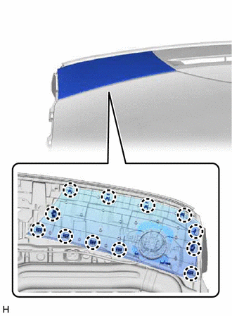
Attach the claw to install the No. 2 instrument panel speaker panel sub-assembly.
-
-
INSTALL NO. 1 INSTRUMENT PANEL SPEAKER PANEL SUB-ASSEMBLY
-
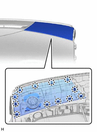
Attach the claw to install the No. 1 instrument panel speaker panel sub-assembly.
-
-
INSTALL CENTER DEFROSTER NOZZLE ASSEMBLY
-
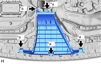
*a Screw <B> Install the center defroster nozzle assembly with the 5 screws <B>.
-