INSTRUMENT PANEL SAFETY PAD(for RHD) REMOVAL
CAUTION / NOTICE / HINT
The necessary procedures (adjustment, calibration, initialization or registration) that must be performed after parts are removed, installed or replaced during the instrument panel safety pad assembly removal/installation are shown below.
| Replacement Part or Procedure | Necessary Procedures | Effects/Inoperative when not Performed | Link |
|---|---|---|---|
| Disconnect cable from negative battery terminal | Drive the vehicle until stop and start control is permitted (approximately 5 to 60 minutes) | Stop and Start System (for 2AR-FE) | |
| Stop and Start System (for 2GR-FKS) | |||
| Memorize steering angle neutral point | Panoramic View Monitor System | ||
| Initialize back door lock | Power Door Lock Control System | ||
| Initialize servo motor | Air Conditioning System | ||
| Reset slide door close position | Power Slide Door System | ||
| Reset back door close position | Power Back Door System |
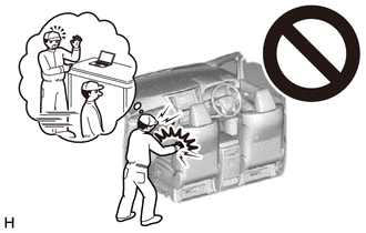
CAUTION:
Some of these service operations affect the SRS airbag system. Read the precautionary notices concerning the SRS airbag system before servicing.
PROCEDURE
-
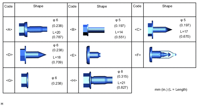
TABLE OF BOLT, SCREW, NUT AND CLIP
Tech Tips
All bolts, screws, nut and clips relevant to installing and removing the instrument panel are shown along with their alphabetic code in the table below.
-
PRECAUTION
Note
After turning the engine switch off, waiting time may be required before disconnecting the cable from the battery terminal. Therefore, make sure to read the disconnecting the cable from the battery terminal notice before proceeding with work
-
DISCONNECT CABLE FROM NEGATIVE BATTERY TERMINAL
CAUTION:
-
Wait at least 90 seconds after disconnecting the cable from the negative (-) battery terminal to disable the SRS system.
-
If the airbag deploys for any reason, it may cause a serious accident.
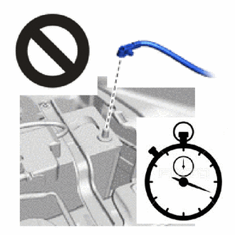
Note
When disconnecting the cable, some systems need to be initialized after the cable is reconnected.
-
-
REMOVE FRONT SEAT ASSEMBLY LH
-
for Manual Seat:
-
for Power Seat:
-
-
REMOVE FRONT SEAT ASSEMBLY RH
-
for Manual Seat:
-
for Power Seat:
-
-
REMOVE REAR NO. 1 SEAT ASSEMBLY LH
-
for Power Captain Seat without Memory:
-
for Power Captain Seat with Memory:
-
for Manual Captain Seat:
-
-
REMOVE REAR NO. 1 SEAT ASSEMBLY RH
-
for Power Captain Seat without Memory:
-
for Power Captain Seat with Memory:
-
for Manual Captain Seat:
-
-
REMOVE CONSOLE BOX ASSEMBLY (for Integrated Console Box Type)
-
REMOVE HEADLIGHT DIMMER SWITCH ASSEMBLY
-
REMOVE CENTER NO. 2 INSTRUMENT CLUSTER FINISH PANEL (for Separate Console Box Type)
-
Put protective tape around the center No. 2 instrument cluster finish panel.
-
Insert moulding remover D at the position shown in the illustration and pull in the direction indicated by the arrow to detach the claw.
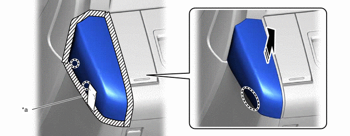
*a Protective Tape - - 
Insert Moulding Remover D Here 
Remove in this Direction -
Place your hands in the gaps created during the above procedure and pull in the direction indicated by the arrows shown in the illustration to detach the claw and clip and remove the center No. 2 instrument cluster panel.
Remove in this Direction - -
-
-
REMOVE CENTER NO. 1 INSTRUMENT CLUSTER FINISH PANEL (for Separate Console Box Type)
-
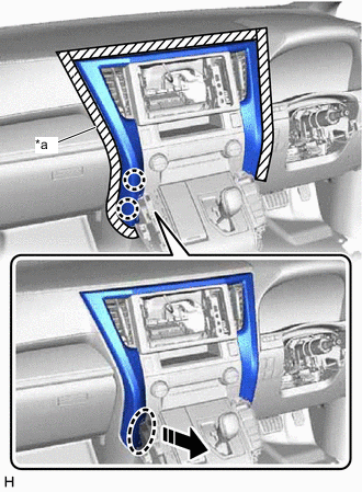
Put protective tape around the center No. 1 instrument cluster finish panel.
-
Insert moulding remover D at the position shown in the illustration and pull in the direction indicated by the arrow to detach the claw.
*a Protective Tape - - Insert Moulding Remover D Here Remove in this Direction -
Place your hands in the gaps created during the above procedure and pull in the direction indicated by the arrows shown in the illustration to detach the claw and clip and remove the center No. 1 instrument cluster panel.
Remove in this Direction - -
-
-
REMOVE UPPER INSTRUMENT PANEL FINISH PANEL
-
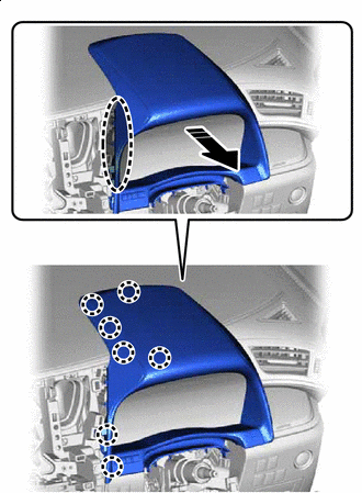
*a Protective Tape Place Hand Here Remove in this Direction Put protective tape around the upper instrument panel finish panel.
-
Place your hand at the position shown in the illustration and pull in the direction indicated by the arrow to detach the claw.
-
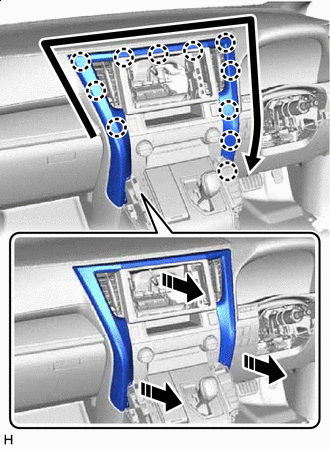
Remove in this Direction 
Order of Removal Place your hand in the gap created during the above procedure and pull in the direction indicated by the arrows shown in the illustration to detach the claw and remove the upper instrument panel finish panel.
-
-
REMOVE CENTER INSTRUMENT CLUSTER FINISH PANEL SUB-ASSEMBLY (w/o Navigation System)
-
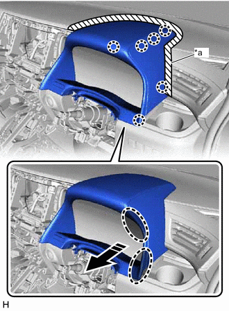
*a Protective Tape Place Hand Here Remove in this Direction Put protective tape around the center instrument cluster finish panel sub-assembly.
-
Place your hand at the position shown in the illustration and pull in the direction indicated by the arrow to detach the claw.
-
Place Hand Here Remove in this Direction Place your hand at the position shown in the illustration and pull in the direction indicated by the arrow to detach the claw.
-
Disconnect the connector and remove the center instrument cluster finish panel sub-assembly.
-
-
REMOVE NO. 4 INSTRUMENT PANEL REGISTER ASSEMBLY (w/ Navigation System)
-
Place Hand Here Remove in this Direction Place your hand at the position shown in the illustration and pull in the direction indicated by the arrow to detach the claw.
-
Remove in this Direction Order of Removal Place your hand in the gap created during the above procedure and pull in the direction indicated by the arrows shown in the illustration to detach the claw and remove the No. 4 instrument panel register assembly.
-
-
REMOVE NO. 3 INSTRUMENT PANEL REGISTER ASSEMBLY (w/ Navigation System)
-
Place Hand Here Remove in this Direction Place your hand at the position shown in the illustration and pull in the direction indicated by the arrow to detach the claw.
-
Remove in this Direction Order of Removal Place your hand in the gap created during the above procedure and pull in the direction indicated by the arrows shown in the illustration to detach the claw and remove the No. 3 instrument panel register assembly.
-
-
REMOVE RADIO TUNER OPENING COVER (w/o Navigation System, w/ Cover)
-
Remove the 4 screws and radio tuner opening cover.
-
-
REMOVE NO. 2 RADIO BRACKET (w/o Navigation System, w/o Cover)
-
Remove the 2 screws and No. 2 radio bracket.
-
-
REMOVE NO. 1 RADIO BRACKET (w/o Navigation System, w/o Cover)
-
Remove the 2 screws and No. 1 radio bracket.
-
-
REMOVE NAVIGATION RECEIVER ASSEMBLY (w/ Navigation System)
-
REMOVE AIR CONDITIONING CONTROL ASSEMBLY
-
REMOVE SHIFT LEVER KNOB SUB-ASSEMBLY
-
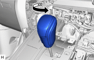
Remove in this Direction Twist the shift lever knob sub-assembly in the direction indicated by the arrow and remove it.
-
-
REMOVE COMBINATION SWITCH ASSEMBLY
-
REMOVE LOWER CENTER INSTRUMENT CLUSTER FINISH PANEL SUB-ASSEMBLY
-
for Integrated Console Box Type:
-
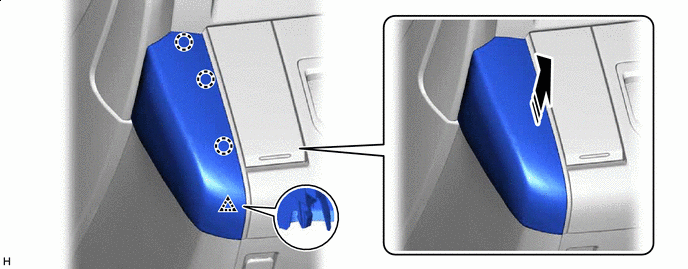
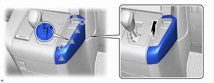
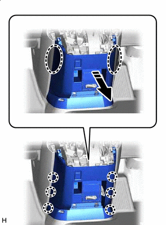
Place Hand Here Remove in this Direction Place your hand at the position shown in the illustration and pull in the direction indicated by the arrow to detach the claw.
-
Fulcrum Position Remove in this Direction With the front part of the lower center instrument cluster finish panel sub-assembly as the fulcrum, lift up the rear of the lower center instrument cluster finish panel sub-assembly and remove it from the shift lever.
-
Remove in this Direction Pull in the direction indicated by the arrow shown in the illustration, disconnect the connector and remove the lower center instrument cluster finish panel sub-assembly.
-
-
for Separate Console Box Type:
-
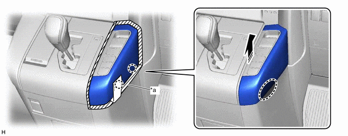
*a Protective Tape Place Hand Here Remove in this Direction Put protective tape around the lower center instrument cluster finish panel sub-assembly.
-
Place your hand at the position shown in the illustration and pull in the direction indicated by the arrow to detach the claw.
-
Fulcrum Position Remove in this Direction With the front part of the lower center instrument cluster finish panel sub-assembly as the fulcrum, lift up the rear of the lower center instrument cluster finish panel sub-assembly and remove it from the shift lever.
-
Remove in this Direction Pull in the direction indicated by the arrow shown in the illustration, disconnect the connector and remove the lower center instrument cluster finish panel sub-assembly.
-
-
-
REMOVE INSTRUMENT PANEL BOX ASSEMBLY (for Separate Console Box Type)
-
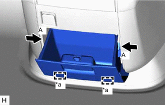
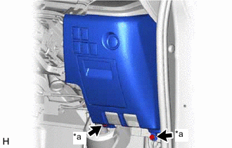
*a Hinge Press the parts labeled A in the illustration in the direction indicated by the arrows to release the stoppers.
-
Detach the hinges and remove the instrument panel box assembly.
-
-
REMOVE INSTRUMENT CLUSTER FINISH PANEL ASSEMBLY (for Separate Console Box Type)
-
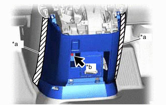
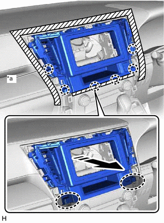
*a Protective Tape *b Bolt <A> Put protective tape around the instrument cluster finish panel assembly.
-
Remove the bolt <A>.
-
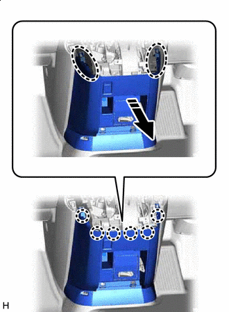
Place Hand Here Remove in this Direction Place your hand at the position shown in the illustration and pull in the direction indicated by the arrow to detach the claw.
-
Place Hand Here Remove in this Direction Place your hands in the gaps created during the above procedure and pull in the direction indicated by the arrow shown in the illustration to detach the claw.
-
Disconnect the connector and remove the instrument cluster finish panel assembly.
-
-
REMOVE INSTRUMENT PANEL FINISH PANEL ASSEMBLY
-
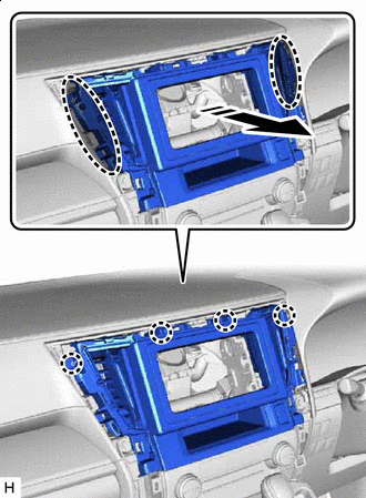
*a Protective Tape Place Hand Here Remove in this Direction Put protective tape around the instrument panel finish panel assembly.
-
Place your hand at the position shown in the illustration and pull in the direction indicated by the arrow to detach the claw.
-
Place Hand Here Remove in this Direction Place your hand at the position shown in the illustration and pull in the direction indicated by the arrow to detach the claw.
-
Disconnect the connector and remove the instrument panel finish panel assembly.
-
-
REMOVE COMBINATION METER ASSEMBLY
-
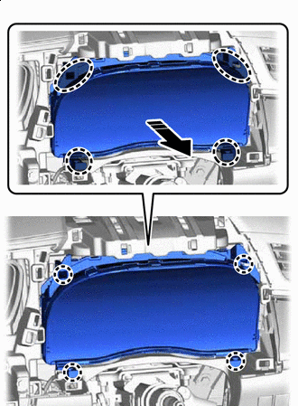
Place Hand Here Remove in this Direction Place your hand at the position shown in the illustration, detach the claw and pull in the direction indicated by the arrow.
-
Disconnect the connector and detach the clamp and remove the combination meter assembly.
-
-
REMOVE COWL SIDE TRIM BOARD RH
-
REMOVE NO. 1 INSTRUMENT PANEL UNDER COVER SUB-ASSEMBLY
-
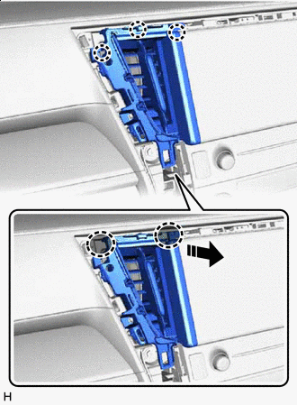
*a Screw <B> Remove the 2 screws <B>.
-
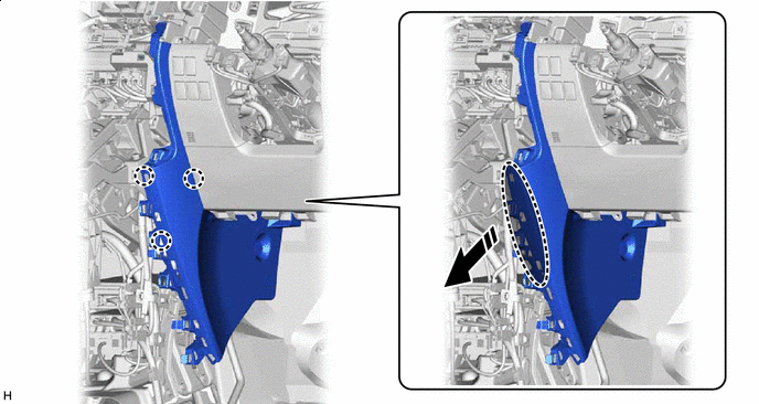
Remove in this Direction Detach the claw and pull in the direction indicated by the arrow.
-
*a Clamp *b Guide Remove in this Direction Disconnect the connector and detach the clamp.
-
Pull in the direction indicated by the arrow shown in the illustration, detach the guide and remove the No. 1 instrument panel under cover sub-assembly.
-
-
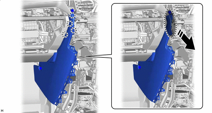
REMOVE LOWER NO. 1 INSTRUMENT PANEL FINISH PANEL
-
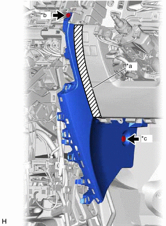
*a Protective Tape *b Screw <C> *c Clip <E> Put protective tape around the lower No. 1 instrument panel finish panel.
-
Remove the screw <C> and clip <E>.
-
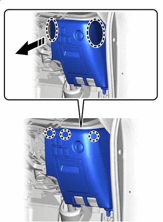
Place your hand at the position shown in the illustration and pull in the direction indicated by the arrow to detach the claw.
Place Hand Here Remove in this Direction -
Place your hand at the position shown in the illustration and pull in the direction indicated by the arrow to detach the claw and remove the lower No. 1 instrument panel finish panel.
Place Hand Here Remove in this Direction
-
-
REMOVE LOWER NO. 1 INSTRUMENT PANEL AIRBAG ASSEMBLY
-
REMOVE NO. 1 SWITCH HOLE BASE
-
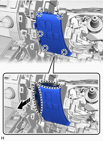
Place Hand Here Remove in this Direction Place your hand at the position shown in the illustration and pull in the direction indicated by the arrow to detach the claw.
-
Disconnect the connector and remove the No. 1 switch hole base.
-
-
REMOVE LOWER INSTRUMENT PANEL FINISH PANEL ASSEMBLY
-
*a Bolt <A> Remove the 2 bolts <A>.
-
Place Hand Here Remove in this Direction Order of Removal Place your hand at the position shown in the illustration and pull in the direction indicated by the arrow to detach the claw in the direction indicated by the arrow.
-
Place Hand Here Remove in this Direction Place your hands in the gaps created during the above procedure and pull in the direction indicated by the arrows shown in the illustration to detach the claw.
-
Disconnect the connector.
-
Detach the claw and guide, disconnect the hood lock control lever sub-assembly and fuel lid lock open lever, and then remove the lower instrument panel finish panel assembly.
-
-
REMOVE INSTRUMENT PANEL CUP HOLDER
-
*a Protective Tape *b Screw <B> Put protective tape around the instrument panel cup holder.
-
Remove the 2 screws <B>.
-
Insert Moulding Remover D Here Remove in this Direction Insert moulding remover D at the position shown in the illustration, pull in the direction indicated by the arrow and place your finger in the gap to detach the claw and remove the instrument panel cup holder.
-
-
REMOVE GLOVE COMPARTMENT DOOR ASSEMBLY
-
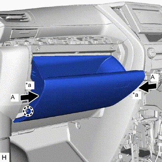
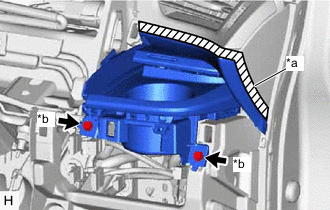
*a Stopper Open the glove compartment door assembly, detach the claw and disconnect the glove compartment door stopper sub-assembly.
-
Push the parts labeled A in the illustration in the direction indicated by the arrows and remove the stoppers.
-
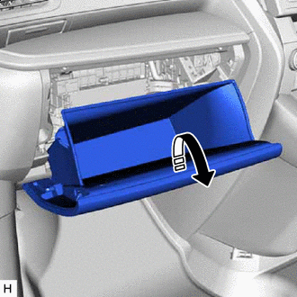
Lowering Direction With the hinge of the glove compartment door assembly as the fulcrum, rotate and lower the glove compartment door assembly until it contacts the instrument panel safety pad assembly.
-
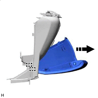
Remove in this Direction Pull in the direction indicated by the arrow shown in the illustration to detach the hinge and remove the glove compartment door assembly.
Tech Tips
Make sure to position the glove compartment door assembly at an almost fully open position in order to remove it.
-
-
REMOVE GLOVE COMPARTMENT DOOR STOPPER SUB-ASSEMBLY
-
Detach the claw and remove the glove compartment door stopper sub-assembly.
-
-
REMOVE NO. 3 INSTRUMENT CLUSTER FINISH PANEL GARNISH
-
for VIP Captain Seat:
-
*a Protective Tape Place Hand Here Remove in this Direction Put protective tape around the No. 3 instrument cluster finish panel garnish.
-
Place your hand at the position shown in the illustration and pull in the direction indicated by the arrow to detach the claw.
-
Remove in this Direction Order of Removal Place your hand in the gap created during the above procedures and pull in the direction indicated by the arrow shown in the illustration to detach the claw and remove the No. 3 instrument cluster finish panel garnish.
-
-
except VIP Captain Seat:
-

*a Protective Tape Place Hand Here Remove in this Direction Put protective tape around the No. 3 instrument cluster finish panel garnish.
-
Place your hand at the position shown in the illustration and pull in the direction indicated by the arrow to detach the claw.
-
Remove in this Direction Order of Removal Place your hand in the gap created during the above procedures and pull in the direction indicated by the arrow shown in the illustration to detach the claw and remove the No. 3 instrument cluster finish panel garnish.
-
-
-
REMOVE COWL SIDE TRIM BOARD LH
-
REMOVE NO. 2 INSTRUMENT PANEL UNDER COVER SUB-ASSEMBLY
-
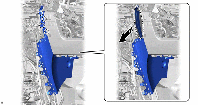
Remove in this Direction Detach the claw and pull in the direction indicated by the arrow.
-
Remove in this Direction Pull in the direction indicated by the arrow shown in the illustration to detach the guide.
-
Remove in this Direction Lower the right side of the No. 2 instrument panel under cover sub-assembly, disconnect the connector and pull in the direction indicated by the arrow shown in the illustration to remove the No. 2 instrument panel under cover sub-assembly.
-
-
REMOVE LOWER NO. 2 INSTRUMENT PANEL FINISH PANEL
-
*a Protective Tape *b Screw <C> *c Clip <E> Put protective tape around the lower No. 2 instrument panel finish panel.
-
Remove the screw <C> and clip <E>.
-
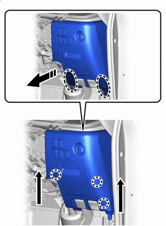
Place your hand at the position shown in the illustration and pull in the direction indicated by the arrow to detach the claw.
Place Hand Here Remove in this Direction -
Place your hand at the position shown in the illustration and pull in the direction indicated by the arrow to detach the claw and remove the lower No. 2 instrument panel finish panel.
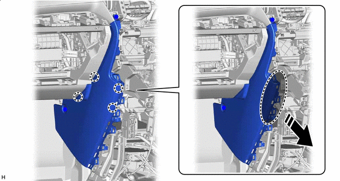
Place Hand Here Remove in this Direction
-
-
REMOVE LOWER INSTRUMENT PANEL
-
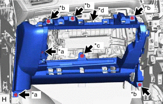
*a Bolt <A> *b Screw <C> *c Screw <D> *d Connector Remove the 2 bolts <A>, 4 screws <C> and screw <D>.
-
Disconnect the connector.
-
Place Hand Here Remove in this Direction Place your hand at the position shown in the illustration and pull in the direction indicated by the arrow to detach the claw and remove the lower instrument panel.
-
-
REMOVE ASSIST GRIP PLUG
-
REMOVE PILLAR ASSIST GRIP ASSEMBLY
-
REMOVE FRONT PILLAR GARNISH LH
-
REMOVE FRONT PILLAR GARNISH RH
-
REMOVE LOWER FRONT PILLAR GARNISH LH
-
REMOVE LOWER FRONT PILLAR GARNISH RH
-
DISCONNECT TRANSMISSION CONTROL CABLE ASSEMBLY
-
REMOVE SHIFT LEVER ASSEMBLY
-
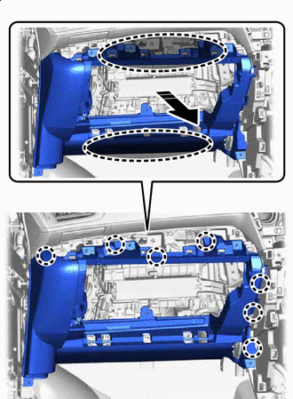
REMOVE INSTRUMENT PANEL SAFETY PAD ASSEMBLY
-
w/o Navigation System:
-
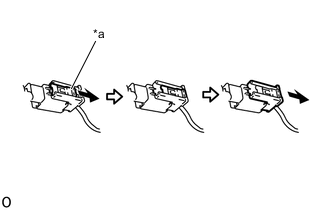
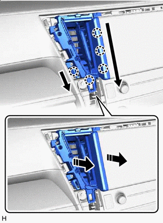
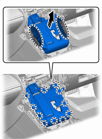
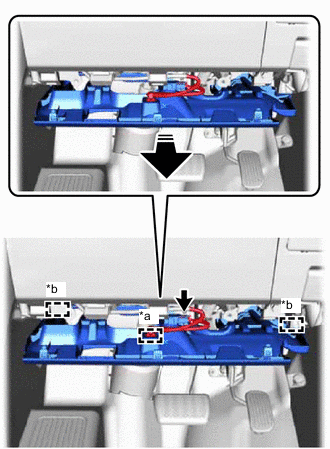
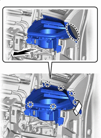
*a Lock Slider Pull and slide the lock slider in the direction indicated by the arrow to release the connector lock and disconnect the passenger airbag connector.
Note
When handling the passenger airbag connector, take care not to damage the airbag wire harness.
-
Disconnect the connector and detach the clamp.
-
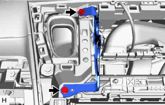
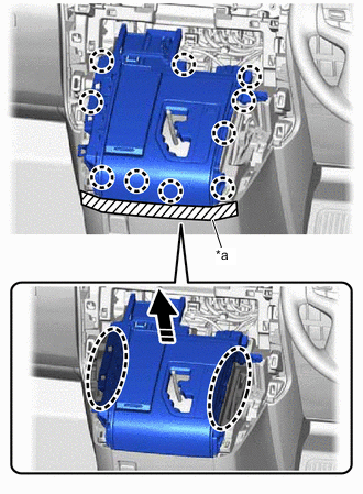
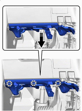
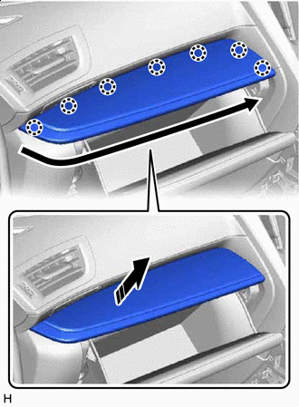
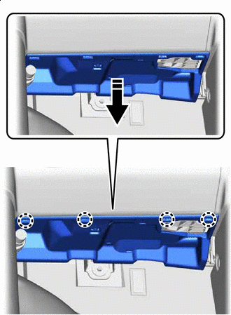
Remove the 8 bolts <A>, 2 clips <F> and 4 nuts <G>.
-
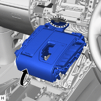
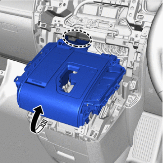
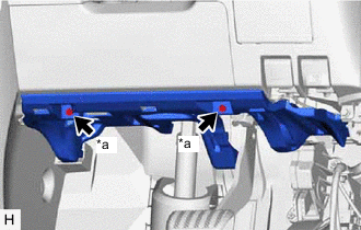
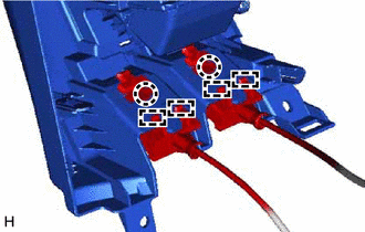
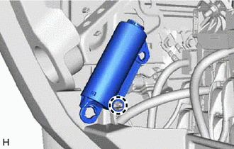
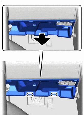
Remove the 2 passenger airbag installation bolts <H>.
-
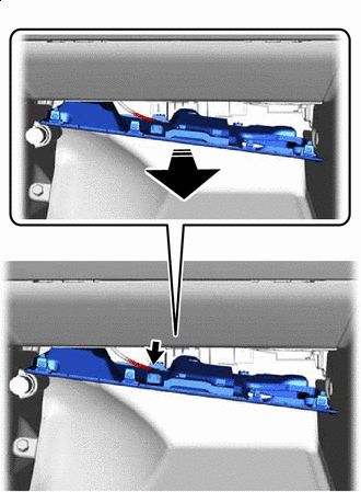
Detach the guide.
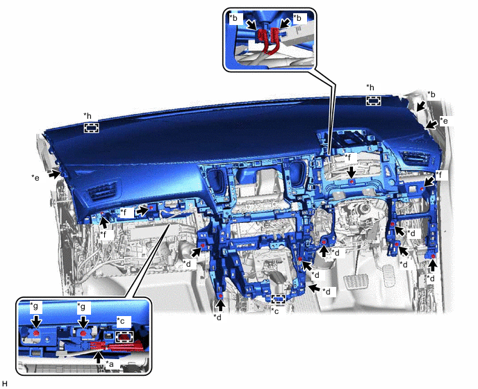
*a Passenger Airbag Connector *b Connector *c Clamp *d Bolt <A> *e Clip <F> *f Nut <G> *g Passenger Airbag Installation Bolt <H> *h Guide
-
-
w/ Navigation System:
-
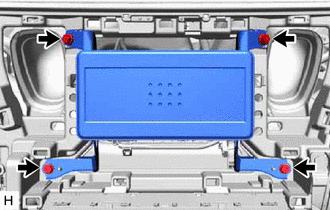
*a Lock Slider Pull and slide the lock slider in the direction indicated by the arrow to release the connector lock and disconnect the passenger airbag connector.
Note
When handling the passenger airbag connector, take care not to damage the airbag wire harness.
-
Disconnect the connector and detach the clamp.
-
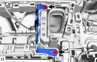
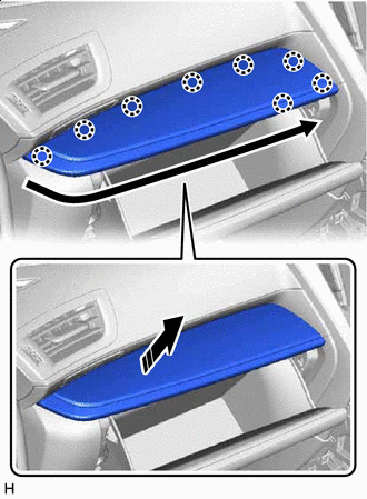
Remove the 8 bolts <A>, 2 clips <F> and 4 nuts <G>.
-
Remove the 2 passenger airbag installation bolts <H>.
-
Detach the guide.
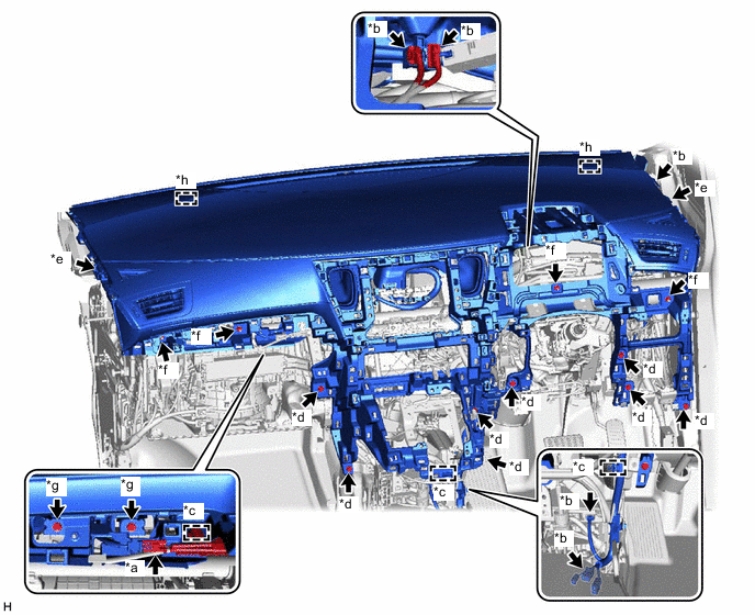
*a Passenger Airbag Connector *b Connector *c Clamp *d Bolt <A> *e Clip <F> *f Nut <G> *g Passenger Airbag Installation Bolt <H> *h Guide
-
-
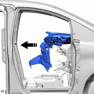
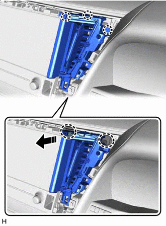
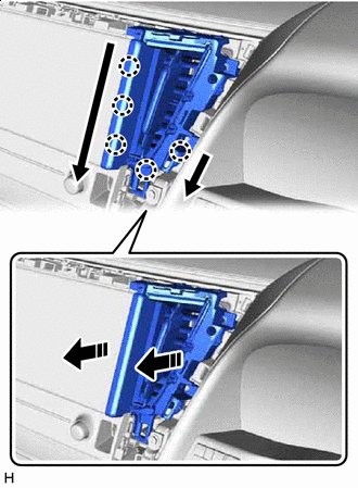
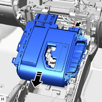
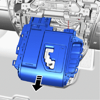
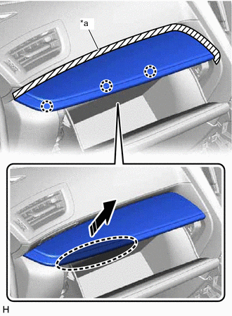
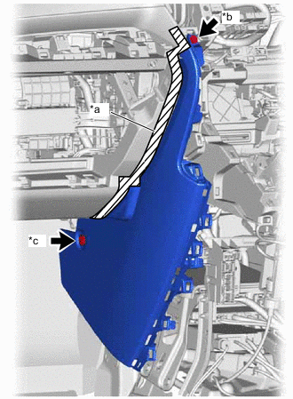
Movement Direction Pull the instrument panel safety pad assembly in the direction indicated by the arrow shown in the illustration.
-
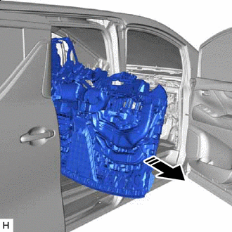
Remove in this Direction Remove the instrument panel safety pad assembly from the slide door opening.
Note
-
Make sure that the instrument panel safety pad assembly does not get caught on anything as it may become bent or damaged.
-
Do not damage the instrument panel safety pad assembly or vehicle interior.
-
-