CONDENSER INSTALLATION
PROCEDURE
-
INSTALL NO. 1 COOLER CONDENSER CUSHION
-
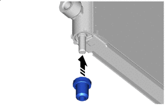

Install in this Direction Install the 4 No. 1 cooler condenser cushions.
-
-
INSTALL COOLER CONDENSER ASSEMBLY
-
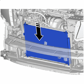
Install in this Direction Insert the cooler condenser assembly from the top.
Tech Tips
If the cooler condenser assembly is replaced with a new one, add compressor oil to the new cooler condenser assembly.
Capacity 40 cc (1.35 fl.oz) Compressor Oil ND-OIL 8 or equivalent
-
-
INSTALL NO. 2 FAN SHROUD (for 2GR-FE)
-
INSTALL NO. 2 FAN SHROUD (for 2AR-FE)
-
INSTALL HOOD LOCK SUPPORT BRACE SUB-ASSEMBLY
-
INSTALL RADIATOR UPPER SUPPORT SUB-ASSEMBLY (for 2GR-FE)
-
INSTALL RADIATOR UPPER SUPPORT SUB-ASSEMBLY (for 2AR-FE)
-
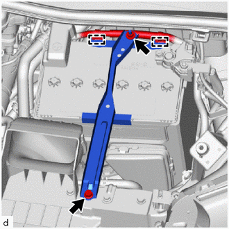
CONNECT NO. 1 WATER BY-PASS PIPE
-
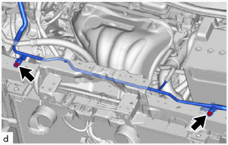
Connect the No. 1 water by-pass pipe with the 2 bolts.
- Torque:
- 12 N*m { 122 kgf*cm, 9 ft.*lbf }
-
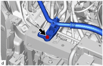
Connect the No. 1 cooler refrigerant suction hose with the bolt.
- Torque:
- 9.8 N*m { 100 kgf*cm, 87 in.*lbf }
-
-
INSTALL NO. 2 FRONT BUMPER SIDE SEAL RH (for 2GR-FE)
-
for ALPHARD:
-
for VELLFIRE:
-
-
INSTALL NO. 2 FRONT BUMPER SIDE SEAL RH (for 2AR-FE)
-
for ALPHARD:
-
for VELLFIRE:
-
-
INSTALL NO. 2 FRONT BUMPER SIDE SEAL LH (for 2GR-FE)
-
for ALPHARD:
-
for VELLFIRE:
-
-
INSTALL NO. 2 FRONT BUMPER SIDE SEAL LH (for 2AR-FE)
-
for ALPHARD:
-
for VELLFIRE:
-
-
INSTALL NO. 1 AIR CLEANER INLET (for 2GR-FE)
-
INSTALL NO. 1 AIR CLEANER INLET (for 2AR-FE)
-
INSTALL HOOD LOCK ASSEMBLY (for LHD)
-
INSTALL HOOD LOCK ASSEMBLY (for RHD)
-
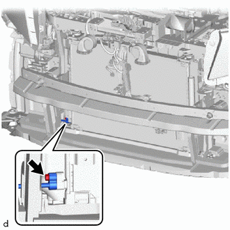
INSTALL BATTERY CLAMP SUB-ASSEMBLY
-
Install the battery clamp sub-assembly with the bolt and nut.
- Torque:
- Nut
- 4.9 N*m { 50 kgf*cm, 43 in.*lbf }
- Bolt
- 21 N*m { 214 kgf*cm, 15 ft.*lbf }
-
Attach the clamp to connect the battery positive terminal.
-
-
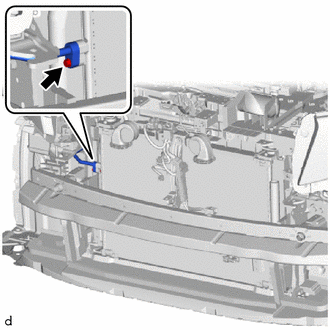
CONNECT NO. 2 AIR CONDITIONER TUBE AND ACCESSORY ASSEMBLY
-
Remove the vinyl tape from the No. 2 air conditioner tube and accessory assembly and the connecting part of the cooler condenser assembly.
-
Sufficiently apply compressor oil to a new O-ring and the fitting surface of the No. 2 air conditioner tube and accessory assembly.
Compressor Oil ND-OIL 8 or equivalent -
Install the O-ring to the No. 2 air conditioner tube and accessory assembly.
Note
Keep the O-rings and O-ring fitting surfaces free of foreign matter.
-
Connect the No. 2 air conditioner tube and accessory assembly to the cooler condenser assembly with the bolt.
- Torque:
- 5.4 N*m { 55 kgf*cm, 48 in.*lbf }
-
-
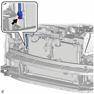
CONNECT NO. 3 AIR CONDITIONER TUBE AND ACCESSORY ASSEMBLY (for 2GR-FE)
-
Remove the vinyl tape from the No. 3 air conditioner tube and accessory assembly and the connecting part of the cooler condenser assembly.
-
Sufficiently apply compressor oil to a new O-ring and the fitting surface of the No. 3 air conditioner tube and accessory assembly.
Compressor Oil ND-OIL 8 or equivalent -
Install the O-ring to the No. 3 air conditioner tube and accessory assembly.
Note
Keep the O-rings and O-ring fitting surfaces free of foreign matter.
-
Connect the No. 3 air conditioner tube and accessory assembly to the cooler condenser assembly with the bolt.
- Torque:
- 5.4 N*m { 55 kgf*cm, 48 in.*lbf }
-
-
CONNECT NO. 1 COOLER REFRIGERANT DISCHARGE HOSE (for 2AR-FE)
-
Remove the vinyl tape from the No. 1 cooler refrigerant discharge hose and the connecting part of the cooler condenser assembly.
-
Sufficiently apply compressor oil to a new O-ring and the fitting surface of the No. 1 cooler refrigerant discharge hose.
Compressor Oil ND-OIL 8 or equivalent -
Install the O-ring to the No. 1 cooler refrigerant discharge hose.
Note
Keep the O-rings and O-ring fitting surfaces free of foreign matter.
-
Connect the No. 1 cooler refrigerant discharge hose to the condenser assembly with the bolt.
- Torque:
- 5.4 N*m { 55 kgf*cm, 48 in.*lbf }
-
-
INSTALL FRONT BUMPER ASSEMBLY (for ALPHARD)
-
INSTALL FRONT BUMPER ASSEMBLY (for VELLFIRE)
-
CHARGE AIR CONDITIONING SYSTEM WITH REFRIGERANT
-
WARM UP ENGINE
-
INSPECT FOR REFRIGERANT LEAK
-
INSPECT HOOD SUB-ASSEMBLY
-
ADJUST HOOD SUB-ASSEMBLY