FRONT SEAT ASSEMBLY(for Driver Side Power Seat) INSTALLATION
CAUTION / NOTICE / HINT
CAUTION:
-
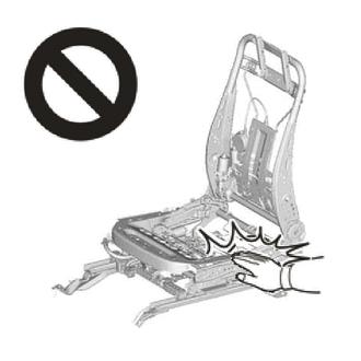
Wear protective gloves. Sharp areas on the parts may injure your hands.
-
There is risk of injury.
Tech Tips
-
Use the same procedure for RHD and LHD vehicles.
-
The procedure listed below is for LHD vehicles.
PROCEDURE
-
INSTALL FRONT SEAT ASSEMBLY LH
-
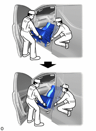
Place the front seat assembly LH in the vehicle, as shown in the illustration.
Note
-
2 or more people are required when carrying the front seat assembly LH out of the vehicle.
-
Protect the front seat legs.
-
Do not damage the front seat assembly LH, body exterior or interior parts.
-
-
Tilt the front seat assembly LH toward the rear of the vehicle.
Note
Do not damage the front seat assembly LH or interior parts.
-
Connect the connector.
-
Connect the front seat airbag assembly LH connector under the front seat assembly LH.
-
Before connecting the connector, check that the position of the housing lock is correct as shown in the illustration.
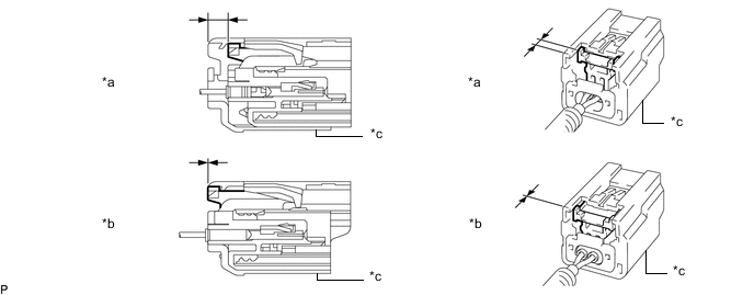
*a Correct *b Incorrect *c Yellow CPA - - -
Be sure to engage the connectors until they are locked (when locking, make sure that a click sound can be heard).
Note
-
Be careful not to damage the connector or wire harness of the front seat airbag assembly LH.
-
When connecting the connector, make sure to push it straight in.
-
Do not hold any parts other than the yellow CPA when connecting the connector.
-
If the upper portion of the yellow CPA is held when connecting the connector, the partial connection prevention mechanism will not function due to deformation of the yellow CPA. Therefore, hold the sides of the yellow CPA.
-
-
-
Align the adjuster pin of the front seat assembly LH with the hole in the body.
-
Temporarily install the front seat assembly LH with the 4 bolts.
-
Connect the cable to the negative (-) battery terminal.
Note
When disconnecting the cable, some systems need to be initialized after the cable is reconnected.
-
Operate the power seat switch knob LH (for Slide) to slide the front seat assembly LH to the rearmost position.
-
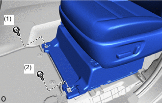
Tighten the 2 bolts on the front side of the front seat assembly LH in the order shown in the illustration.
- Torque:
- 39 N*m { 398 kgf*cm, 29 ft.*lbf }
-
Operate the power seat switch knob LH (for Slide) to slide the front seat assembly RH to the frontmost position.
-
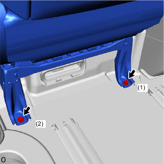
Tighten the 2 bolts on the rear side of the front seat assembly LH in the order shown in the illustration.
- Torque:
- 39 N*m { 398 kgf*cm, 29 ft.*lbf }
-
-
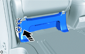
INSTALL FRONT SEAT NO. 1 LEG COVER
-
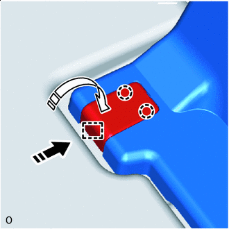

Installation in this Direction (1) 
Installation in this Direction (2) for Inner Side:
-
Push in installation direction (1) shown in the illustration and attach the hook to install the front seat No.1 seat leg cover.
-
Push the part closed in installation direction (2) shown in the illustration to attach the claw.
-
-
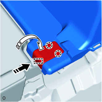
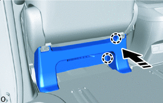
Installation in this Direction (1) Installation in this Direction (2) for Outer Side:
-
Push in installation direction (1) shown in the illustration and attach the hook to install the front seat No.1 seat leg cover.
-
Push the part closed in installation direction (2) shown in the illustration to attach the claw.
-
-
-
INSTALL RH SEAT FRONT SEAT LEG COVER
-
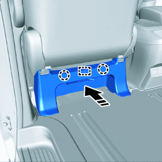
Installation in this Direction Operate the power seat switch knob LH (for Slide) to slide the front seat assembly LH to the frontmost position.
-
Push in the installation direction shown in the illustration and align the claw and guide.
-
Installation in this Direction Push in the installation direction shown in the illustration to attach the claw.
-
Installation in this Direction Push in the installation direction shown in the illustration to attach the claw and install the front seat leg cover LH.
-
Return the floor carpet to its original position.
-
-
INSTALL NO. 3 FLOOR CARPET MOULDING
-
Temporarily install the 2 No. 3 floor carpet mouldings.
-
Using a screwdriver, rotate the screw portion 90° clockwise and lock it to install the 2 No. 3 floor carpet mouldings.
-
-
INSTALL REAR DOOR SCUFF PLATE LH
-
INSTALL DOOR SCUFF PLATE ASSEMBLY LH
-
INSTALL COWL SIDE TRIM BOARD LH
-
INSPECT FRONT SEAT ASSEMBLY
-
INSPECT SRS WARNING LIGHT
-
INSPECT SEAT BELT WARNING LIGHT
-
INSPECT SEAT HEATER SYSTEM
-
INSPECT CLIMATE CONTROL SEAT SYSTEM