CLIMATE CONTROL SEAT SYSTEM Climate Control System does not Operate on Passenger Side
DESCRIPTION
The air conditioning amplifier assembly receives refreshing seat switch position signals when the engine switch is on (IG), and then transmits airflow amount signals to each seat climate blower.
WIRING DIAGRAM
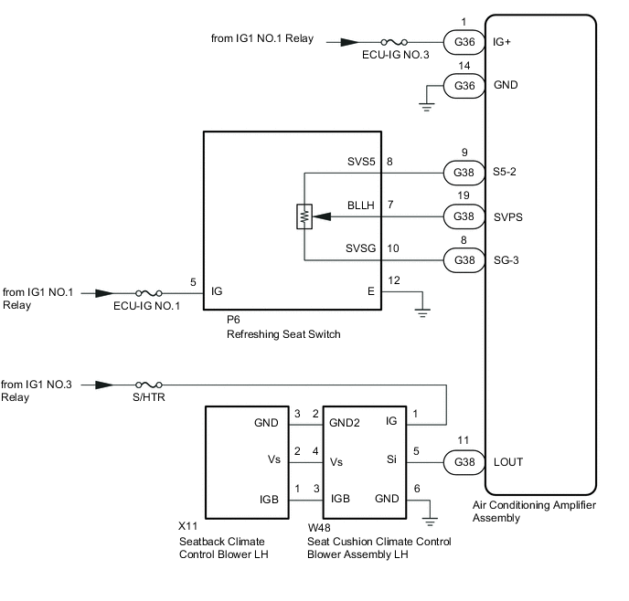
Figure 1. for LHD:
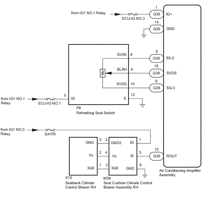
Figure 2. for RHD:
CAUTION / NOTICE / HINT
Note
Inspect the fuses for circuits related to this system before performing the following procedure.
PROCEDURE
-
CHECK CLIMATE CONTROL SEAT OPERATION (for Front Passenger Seat)
-
Check the climate control seat operation again.
Result Result Proceed to Only seatback climate control blower (front passenger seat) does not operate A Only seat cushion climate control blower assembly (front passenger seat) does not operate B Both climate control blowers (front passenger seat) do not operate C
B 
REPLACE SEAT CUSHION CLIMATE CONTROL BLOWER ASSEMBLY (FRONT PASSENGER SEAT) Click here
C 
INSPECT REFRESHING SEAT SWITCH Click here
A 
-
-
CHECK HARNESS AND CONNECTOR (SEAT CUSHION CLIMATE CONTROL BLOWER ASSEMBLY (for Front Passenger Seat) - SEATBACK CLIMATE CONTROL BLOWER (for Front Passenger Seat))
-
for LHD:
-
Disconnect the W36 seat cushion climate control blower assembly RH connector.
-
Disconnect the X10 seatback climate control blower RH connector.
-
Measure the resistance according to the value(s) in the table below.
Standard Resistance Tester Connection Condition Specified Condition W36-2 (GND2) - X10-3 (GND) Always Below 1 Ω W36-2 (GND2) or X10-3 (GND) - Body ground Always 10 kΩ or higher W36-4 (Vs) - X10-2 (Vs) Always Below 1 Ω W36-4 (Vs) or X10-2 (Vs) - Body ground Always 10 kΩ or higher W36-3 (IGB) - X10-1 (IGB) Always Below 1 Ω W36-3 (IGB) or X10-1 (IGB) - Body ground Always 10 kΩ or higher
-
-
for RHD:
-
Disconnect the W48 seat cushion climate control blower assembly LH connector.
-
Disconnect the X11 seatback climate control blower LH connector.
-
Measure the resistance according to the value(s) in the table below.
Standard Resistance Tester Connection Condition Specified Condition W48-2 (GND2) - X11-3 (GND) Always Below 1 Ω W48-2 (GND2) or X11-3 (GND) - Body ground Always 10 kΩ or higher W48-4 (Vs) - X11-2 (Vs) Always Below 1 Ω W48-4 (Vs) or X11-2 (Vs) - Body ground Always 10 kΩ or higher W48-3 (IGB) - X11-1 (IGB) Always Below 1 Ω W48-3 (IGB) or X11-1 (IGB) - Body ground Always 10 kΩ or higher
Result Proceed to OK NG -
NG
REPAIR OR REPLACE HARNESS OR CONNECTOR
OK
-
-
REPLACE SEATBACK CLIMATE CONTROL BLOWER (for Front Passenger Seat)
-
Temporarily replace the seatback climate control blower (for Front Passenger Seat) with a new or known good one.
Result Proceed to NEXT
NEXT
-
-
CHECK CLIMATE CONTROL SEAT OPERATION (for Front Passenger Seat)
-
Check the climate control seat operation.
OK The climate control seat operates normally. Result Proceed to OK NG
OK
END (SEATBACK CLIMATE CONTROL BLOWER (for Front Passenger Seat) WAS DEFECTIVE)
NG
REPLACE SEAT CLIMATE CONTROL BLOWER (for Front Passenger Seat) Click here
-
-
INSPECT REFRESHING SEAT SWITCH
-
Remove the refreshing seat switch.
-
Inspect the refreshing seat switch.
Result Proceed to OK NG
NG
REPLACE REFRESHING SEAT SWITCH Click here
OK
-
-
CHECK HARNESS AND CONNECTOR (REFRESHING SEAT SWITCH - BATTERY AND BODY GROUND)
-
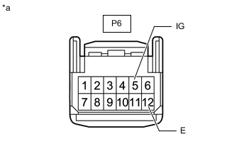
*a Front view of wire harness connector
(to Refreshing Seat Switch)
Disconnect the refreshing seat switch connector.
-
Measure the resistance according to the value(s) in the table below.
Standard Resistance Tester Connection Condition Specified Condition P6-12 (E) - Body ground Always Below 1 Ω -
Measure the voltage according to the value(s) in the table below.
Standard Voltage Tester Connection Switch Condition Specified Condition P6-5 (IG) - Body ground Engine switch on (IG) 11 to 14 V Engine switch off Below 1 V Result Proceed to OK NG
NG
REPAIR OR REPLACE HARNESS OR CONNECTOR
OK
-
-
CHECK HARNESS AND CONNECTOR (REFRESHING SEAT SWITCH - AIR CONDITIONING AMPLIFIER ASSEMBLY)
-
Disconnect the P6 refreshing seat switch connector.
-
Disconnect the G38 air conditioning amplifier assembly connector.
-
Measure the resistance according to the value(s) in the table below.
Standard Resistance for LHD Tester Connection Condition Specified Condition P6-8 (SVS5) - G38-9 (S5-2) Always Below 1 Ω P6-8 (SVS5) or G38-9 (S5-2) - Body ground Always 10 kΩ or higher P6-9 (BLRH) - G38-18 (SVDS) Always Below 1 Ω P6-9 (BLRH) or G38-18 (SVDS) - Body ground Always 10 kΩ or higher P6-10 (SVSG) - G38-8 (SG-3) Always Below 1 Ω P6-10 (SVSG) or G38-8 (SG-3) - Body ground Always 10 kΩ or higher for RHD Tester Connection Condition Specified Condition P6-7 (BLLH) - G38-19 (SVPS) Always Below 1 Ω P6-7 (BLLH) or G38-19 (SVPS) - Body ground Always 10 kΩ or higher P6-8 (SVS5) - G38-9 (S5-2) Always Below 1 Ω P6-8 (SVS5) or G38-9 (S5-2) - Body ground Always 10 kΩ or higher P6-10 (SVSG) - G38-8 (SG-3) Always Below 1 Ω P6-10 (SVSG) or G38-8 (SG-3) - Body ground Always 10 kΩ or higher Result Proceed to OK NG
NG
REPAIR OR REPLACE HARNESS OR CONNECTOR
OK
-
-
CHECK HARNESS AND CONNECTOR (SEAT CUSHION CLIMATE CONTROL BLOWER ASSEMBLY (for Front Passenger Seat) - BATTERY AND BODY GROUND)
-

*a Front view of wire harness connector
(to Seat Cushion Climate Control Blower Assembly RH)
for LHD:
-
Disconnect the seat cushion climate control blower assembly RH connector.
-
Measure the resistance according to the value(s) in the table below.
Standard Resistance Tester Connection Condition Specified Condition W36-6 (GND) - Body ground Always Below 1 Ω -
Measure the voltage according to the value(s) in the table below.
Standard Voltage Tester Connection Switch Condition Specified Condition W36-1 (IG) - Body ground Engine switch on (IG) 11 to 14 V Engine switch off Below 1 V
-
-
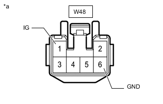
*a Front view of wire harness connector
(to Seat Cushion Climate Control Blower Assembly LH)
for RHD:
-
Disconnect the seat cushion climate control blower assembly LH connector.
-
Measure the resistance according to the value(s) in the table below.
Standard Resistance Tester Connection Condition Specified Condition W48-6 (GND) - Body ground Always Below 1 Ω -
Measure the voltage according to the value(s) in the table below.
Standard Voltage Tester Connection Switch Condition Specified Condition W48-1 (IG) - Body ground Engine switch on (IG) 11 to 14 V Engine switch off Below 1 V
Result Proceed to OK NG -
NG
REPAIR OR REPLACE HARNESS OR CONNECTOR
OK
-
-
CHECK HARNESS AND CONNECTOR (SEAT CUSHION CLIMATE CONTROL BLOWER ASSEMBLY (for Front Passenger Seat) - AIR CONDITIONING AMPLIFIER ASSEMBLY)
-
for LHD:
-
Disconnect the W36 seat climate control blower RH connector.
-
Disconnect the G38 air conditioning amplifier assembly connector.
-
Measure the resistance according to the value(s) in the table below.
Standard Resistance Tester Connection Condition Specified Condition W36-5 (Si) - G38-10 (ROUT) Always Below 1 Ω W36-5 (Si) or G38-10 (ROUT) - Body ground Always 10 kΩ or higher
-
-
for RHD:
-
Disconnect the W48 seat climate control blower LH connector.
-
Disconnect the G38 air conditioning amplifier assembly connector.
-
Measure the resistance according to the value(s) in the table below.
Standard Resistance Tester Connection Condition Specified Condition W48-5 (Si) - G38-11 (LOUT) Always Below 1 Ω W48-5 (Si) or G38-11 (LOUT) - Body ground Always 10 kΩ or higher
Result Proceed to OK NG -
NG
REPAIR OR REPLACE HARNESS OR CONNECTOR
OK
-
-
CHECK AIR CONDITIONING AMPLIFIER ASSEMBLY
-
Check for pulses according to the value(s) in the table below.
-
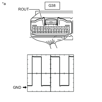
*a Component with harness connected
(Air Conditioning Amplifier Assembly)
for LHD:
Measurement Condition Item Content Tester Connection G38-10 (ROUT) - Body ground Tool Setting 1 V/DIV., 1 ms/DIV. Vehicle Condition
-
Engine switch on (IG)
-
Refreshing seat switch (for RH) on and set to seat blower position
-
-
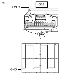
*a Component with harness connected
(Air Conditioning Amplifier Assembly)
for RHD:
Measurement Condition Item Content Tester Connection G38-11 (LOUT) - Body ground Tool Setting 1 V/DIV., 1 ms/DIV. Vehicle Condition
-
Engine switch on (IG)
-
Refreshing seat switch (for LH) on and set to seat blower position
-
OK Waveform is similar to that shown in the illustration. Result Proceed to OK NG -
OK
REPLACE SEAT CUSHION CLIMATE CONTROL BLOWER ASSEMBLY (for Front Passenger Seat) Click here
NG
REPLACE AIR CONDITIONING AMPLIFIER ASSEMBLY Click here
REPLACE AIR CONDITIONING AMPLIFIER ASSEMBLY Click here -