SEAT HEATER SYSTEM TERMINALS OF ECU
-
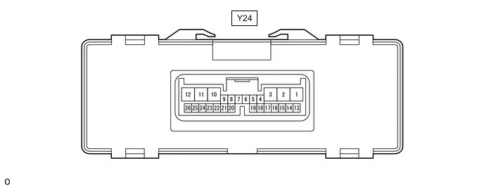
REAR SEAT CLIMATE CONTROL ECU LH
-
Disconnect the Y24 rear seat climate control ECU LH connector.
-
Measure the voltage and resistance according to the value(s) in the table below.
Tester Connection Wiring Color Terminal Description Condition Specified Condition Y24-3 (GND) - Body ground W - Body ground Ground Always Below 1 Ω Y24-12 (IG) - Body ground B - Body ground IG power supply Engine switch on (IG) 11 to 14 V Engine switch off Below 1 V Y24-13 (+B) - Body ground P - Body ground Battery power supply Always 11 to 14 V -
Reconnect the Y24 rear seat climate control ECU LH connector.
-
Measure the voltage according to the value(s) in the table below.
-
Check for pulse generation according to the value(s) in the table below.
Tester Connection Wiring Color Terminal Description Condition Specified Condition Y24-1 (IND1) - Body ground LG - Body ground Seat heater indicator signal
-
Engine switch on (IG)
-
Heated and ventilated seat main switch on and set to seat heater position
Pulse generation Y24-7 (HSWM) - Body ground L - Body ground Heated and ventilated seat main switch signal
-
Engine switch on (IG)
-
Heated and ventilated seat main switch off
11 to 14 V
-
Engine switch on (IG)
-
Heated and ventilated seat main switch on
Below 1 V Y24-11 (HTR+) - Y24-2 (HTR-) Y - L Seat heater drive signal
-
Engine switch on (IG)
-
Heated and ventilated seat main switch off
Below 1 V
-
Engine switch on (IG)
-
Heated and ventilated seat main switch on and set to seat heater position
11 to 14 V Y24-18 (HSWS) - Body ground G - Body ground Heated and ventilated seat main switch volume signal
-
Engine switch on (IG)
-
Heated and ventilated seat main switch on and set to seat heater position
2.5 to 5 V Y24-19 (HSW5) - Y24-20 (HSWG) V - B Heated and ventilated seat main switch output
-
Engine switch on (IG)
-
Heated and ventilated seat main switch off
Below 1 V
-
Engine switch on (IG)
-
Heated and ventilated seat main switch on
4.5 to 5.5 V -
-
-
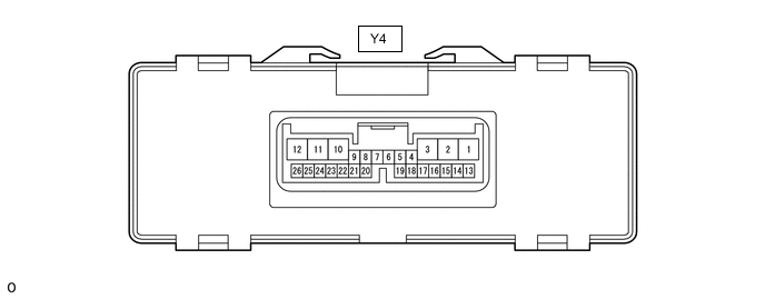
REAR SEAT CLIMATE CONTROL ECU RH
-
Disconnect the Y4 rear seat climate control ECU RH connector.
-
Measure the voltage and resistance according to the value(s) in the table below.
Tester Connection Wiring Color Terminal Description Condition Specified Condition Y4-3 (GND) - Body ground W - Body ground Ground Always Below 1 Ω Y4-12 (IG) - Body ground B - Body ground IG power supply Engine switch on (IG) 11 to 14 V Engine switch off Below 1 V Y4-13 (+B) - Body ground P - Body ground Battery power supply Always 11 to 14 V -
Reconnect the Y4 rear seat climate control ECU RH connector.
-
Measure the voltage according to the value(s) in the table below.
-
Check for pulse generation according to the value(s) in the table below.
Tester Connection Wiring Color Terminal Description Condition Specified Condition Y4-1 (IND1) - Body ground LG - Body ground Seat heater indicator signal
-
Engine switch on (IG)
-
Heated and ventilated seat main switch on and set to seat heater position
Pulse generation Y4-7 (HSWM) - Body ground L - Body ground Heated and ventilated seat main switch signal
-
Engine switch on (IG)
-
Heated and ventilated seat main switch off
11 to 14 V
-
Engine switch on (IG)
-
Heated and ventilated seat main switch on
Below 1 V Y4-11 (HTR+) - Y4-2 (HTR-) Y - L Seat heater drive signal
-
Engine switch on (IG)
-
Heated and ventilated seat main switch off
Below 1 V
-
Engine switch on (IG)
-
Heated and ventilated seat main switch on and set to seat heater position
11 to 14 V Y4-18 (HSWS) - Body ground G - Body ground Heated and ventilated seat main switch volume signal
-
Engine switch on (IG)
-
Heated and ventilated seat main switch on and set to seat heater position
2.5 to 5 V Y4-19 (HSW5) - Y4-20 (HSWG) V - B Heated and ventilated seat main switch output
-
Engine switch on (IG)
-
Heated and ventilated seat main switch off
Below 1 V
-
Engine switch on (IG)
-
Heated and ventilated seat main switch on
4.5 to 5.5 V -
-