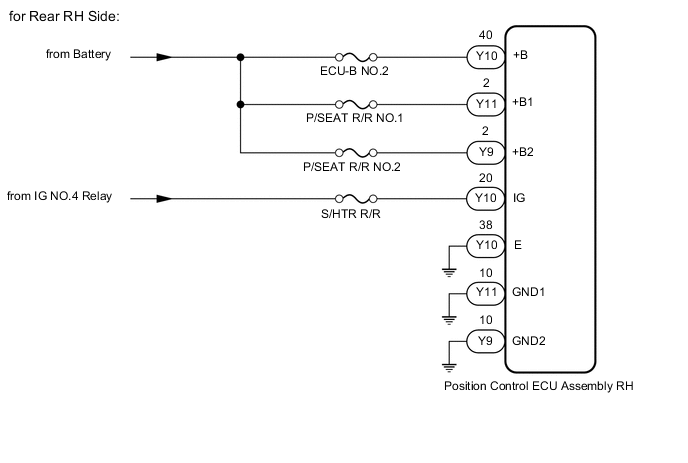
REAR POWER SEAT CONTROL SYSTEM(w/ Memory) Power Source Circuit
WIRING DIAGRAM

CAUTION / NOTICE / HINT
Tech Tips
Inspect the fuses for circuits related to this system before performing the following procedure.
PROCEDURE
-
INSPECT BATTERY VOLTAGE
-
Measure the battery voltage.
Standard voltage 11 to 14 V Tech Tips
If the voltage is below 11 V, recharge or replace the battery before proceeding to the next step.
-
Check the connector connections and terminals to make sure that there are no abnormalities such as loose connections, deformation, etc.
Result Proceed to NEXT
NEXT 
-
-
CHECK HARNESS AND CONNECTOR (POSITION CONTROL ECU ASSEMBLY - BATTERY AND BODY GROUND)
-
Disconnect the Y29, Y30 and Y31 position control ECU assembly LH connectors.
-
Disconnect the Y9, Y10 and Y11 position control ECU assembly RH connectors.
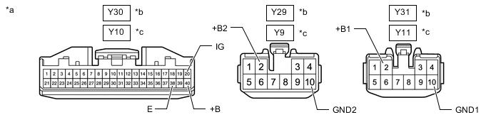
*a Front view of wire harness connector (to Position Control ECU Assembly) *b for Rear LH Side *c for Rear RH Side - - -
Measure the voltage according to the value(s) in the table below.
Standard Voltage for Rear LH Side Tester Connection Condition Specified Condition Y30-40 (+B) - Body ground Always 11 to 14 V Y31-2 (+B1) - Body ground Always 11 to 14 V Y29-2 (+B2) - Body ground Always 11 to 14 V Y30-20 (IG) - Body ground Engine switch off Below 1 V Engine switch on (IG) 11 to 14 V for Rear RH Side Tester Connection Condition Specified Condition Y10-40 (+B) - Body ground Always 11 to 14 V Y11-2 (+B1) - Body ground Always 11 to 14 V Y9-2 (+B2) - Body ground Always 11 to 14 V Y10-20 (IG) - Body ground Engine switch off Below 1 V Engine switch on (IG) 11 to 14 V -
Measure the resistance according to the value(s) in the table below.
Standard Resistance for Rear LH Side Tester Connection Condition Specified Condition Y31-10 (GND1) - Body ground Always Below 1 Ω Y29-10 (GND2) - Body ground Always Below 1 Ω Y30-38 (E) - Body ground Always Below 1 Ω for Rear RH Side Tester Connection Condition Specified Condition Y11-10 (GND1) - Body ground Always Below 1 Ω Y9-10 (GND2) - Body ground Always Below 1 Ω Y10-38 (E) - Body ground Always Below 1 Ω Result Result OK NG
OK 
REPLACE POSITION CONTROL ECU ASSEMBLY LH Click here
NG
REPAIR OR REPLACE HARNESS OR CONNECTOR
-