REAR POWER SEAT CONTROL SYSTEM(w/ Memory) TERMINALS OF ECU
-
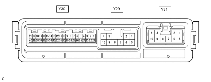
POSITION CONTROL ECU ASSEMBLY LH
-
Disconnect the Y29, Y30 and Y31 position control ECU assembly LH connectors.
-
Measure the resistance and voltage according to the value(s) in the table below.
Terminal No.
(Symbol)
Wiring Color Terminal Description Condition Specified Condition Y30-40 (+B) - Body ground G - Body ground Battery power source Always 11 to 14 V Y31-2 (+B1) - Body ground R - Body ground Battery power source Always 11 to 14 V Y29-2 (+B2) - Body ground L - Body ground Battery power source Always 11 to 14 V Y30-20 (IG) - Body ground R - Body ground IG power source Engine switch on (IG) 11 to 14 V Engine switch off Below 1 V Y31-10 (GND1) - Body ground W-B - Body ground Ground Always Below 1 Ω Y29-10 (GND2) - Body ground B - Body ground Ground Always Below 1 Ω Y30-38 (E) - Body ground W-B - Body ground Ground Always Below 1 Ω -
Reconnect the Y29, Y30 and Y31 position control ECU assembly LH connectors.
-
Measure the voltage according to the value(s) in the table below.
-
Check for pulses according to the value(s) in the table below.
Terminal No.
(Symbol)
Wiring Color Terminal Description Condition Specified Condition Y30-1 (SWS1) - Y30-15 (SWD3) W - LG Rear power seat switch LH (SET) signal Rear power seat switch LH (SET) off → on 11 to 14 V → Below 1 V Y30-2 (SWS2) - Y30-15 (SWD3) B - LG Rear power seat switch LH (M1) signal Rear power seat switch LH (M1) off → on 11 to 14 V → Below 1 V Y30-21 (SWS3) - Y30-15 (SWD3) G - LG Rear power seat switch LH (M2) signal Rear power seat switch LH (M2) off → on 11 to 14 V → Below 1 V Y30-1 (SWS1) - Y30-35 (SWD4) W - SB Rear power seat switch LH (return) signal Rear power seat switch LH (return) off → on 11 to 14 V → Below 1 V Y30-2 (SWS2) - Y30-16 (SWD1) B - R Rear power seat switch LH (ottoman [open]) signal Rear power seat switch LH (ottoman [open]) off → on 11 to 14 V → Below 1 V Y30-2 (SWS2) - Y30-36 (SWD2) B - BE Rear power seat switch LH (ottoman [close]) signal Rear power seat switch LH (ottoman [close]) off → on 11 to 14 V → Below 1 V Y30-21 (SWS3) - Y30-16 (SWD1) G - R Rear power seat switch LH (ottoman [expansion]) signal Rear power seat switch LH (ottoman [expansion]) off → on 11 to 14 V → Below 1 V Y30-21 (SWS3) - Y30-36 (SWD2) G - BE Rear power seat switch LH (ottoman [contraction]) signal Rear power seat switch LH (ottoman [contraction]) off → on 11 to 14 V → Below 1 V Y30-1 (SWS1) - Y30-16 (SWD1) W - R Rear power seat switch LH (reclining [forward]) signal Rear power seat switch LH (reclining [forward]) off → on 11 to 14 V → Below 1 V Y30-1 (SWS1) - Y30-36 (SWD2) W - BE Rear power seat switch LH (reclining (backward)) signal Rear power seat switch LH (reclining [backward]) off → on 11 to 14 V → Below 1 V Y30-7 (WISS) - Body ground GR - Body ground Rear power seat switch LH (walk in switch) (walk in) signal Rear power seat switch LH (walk in switch) (walk in) off → on 11 to 14 V → Below 1 V Y30-30 (WIRS) - Body ground Y - Body ground Rear power seat switch LH (walk in switch) (walk in return) signal Rear power seat switch LH (walk in switch) (walk in return) off → on 11 to 14 V → Below 1 V Y30-4 (WIST) - Body ground B - Body ground Rear control switch LH (walk in) signal Rear control switch LH (walk in) off → on 11 to 14 V → Below 1 V Y30-25 (WIRT) - Body ground P - Body ground Rear control switch LH (walk in return) signal Rear control switch LH (walk in return) off → on 11 to 14 V → Below 1 V Y30-27 (LRS) - Body ground BR - Body ground Rear seat lock open lever sub-assembly LH signal Slide lock release lever LH not operated → operated 11 to 14 V → Below 1 V Y30-6 (BLC) - Body ground B - Body ground Rear left seat belt buckle switch signal Rear left seat belt unfastened → fastened 11 to 14 V → Below 1 V Y30-9 (RTRN) - Body ground G - Body ground Rear power seat return switch LH signal Rear power seat return switch LH off → on 11 to 14 V → Below 1 V Y30-26 (STS) - Body ground R - Body ground Occupant detection sensor signal Occupant not in rear LH seat → occupant in rear LH seat 11 to 14 V → Below 1 V Y30-24 (P) - Body ground L - Body ground P shift position switch signal Shift lever in P → shift lever not in P Below 1 V → 10.6 V Y29-6 (OG1+) - Body ground BE - Body ground Ottoman motor (open/close) operation signal Rear power seat switch LH (ottoman [open]) on 11 to 14 V Y29-9 (OG1-) - Body ground BR - Body ground Ottoman motor (open/close) operation signal Rear power seat switch LH (ottoman [close]) on 11 to 14 V Y31-7 (OTE+) - Body ground P - Body ground Ottoman motor (expansion/contraction) operation signal Rear power seat switch LH (ottoman [expansion]) on 11 to 14 V Y31-3 (OTE-) - Body ground V - Body ground Ottoman motor (expansion/contraction) operation signal Rear power seat switch LH (ottoman [contraction]) on 11 to 14 V Y29-5 (RCL1+) - Body ground G - Body ground Reclining motor (inner side) operation signal Rear power seat switch LH (reclining [forward]) on 11 to 14 V Y29-4 (RCL1-) - Body ground B - Body ground Reclining motor (inner side) operation signal Rear power seat switch LH (reclining [backward]) on 11 to 14 V Y31-5 (RCL2+) - Body ground R - Body ground Reclining motor (outer side) operation signal Rear power seat switch LH (reclining [forward]) on 11 to 14 V Y31-4 (RCL2-) - Body ground L - Body ground Reclining motor (outer side) operation signal Rear power seat switch LH (reclining [backward]) on 11 to 14 V Y29-7 (LR+) - Body ground W - Body ground Slide lock motor operation signal Slide lock operation performed 11 to 14 V Y29-3 (LR-) - Body ground Y - Body ground Slide lock motor operation signal Slide lock release operation performed 11 to 14 V Y30-19 (PVC1) - Y30-11 (SG) SB - R Reclining and ottoman (open/close) position sensor power source Rear power seat switch LH (reclining or ottoman [open/close]) on 5 to 6.6 V Y30-32 (SRCL) - Body ground G - Body ground Reclining position signal Rear power seat switch LH (reclining) on Pulse generation Y30-12 (SOTG) - Body ground Y - Body ground Ottoman (open/close) position signal Rear power seat switch LH (ottoman [open/close]) on Pulse generation Y30-14 (SOTE) - Body ground BR - Body ground Ottoman (expansion/contraction) position signal Rear power seat switch LH (ottoman [expansion/contraction]) on Pulse generation Y30-28 (LSW1) - Body ground B - Body ground No. 1 limit switch signal Slide lock release lever LH not operated → operated Below 1 V → 11 to 14 V Y30-29 (LSW3) - Body ground Y - Body ground No. 2 limit switch signal Slide lock release lever LH not operated → operated Below 1 V → 11 to 14 V
-
-
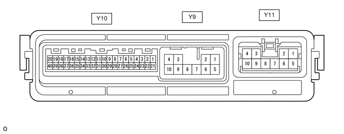
POSITION CONTROL ECU ASSEMBLY RH
-
Disconnect the Y9, Y10 and Y11 position control ECU assembly RH connectors.
-
Measure the resistance and voltage according to the value(s) in the table below.
Terminal No.
(Symbol)
Wiring Color Terminal Description Condition Specified Condition Y10-40 (+B) - Body ground G - Body ground Battery power source Always 11 to 14 V Y11-2 (+B1) - Body ground R - Body ground Battery power source Always 11 to 14 V Y9-2 (+B2) - Body ground L - Body ground Battery power source Always 11 to 14 V Y10-20 (IG) - Body ground R - Body ground IG power source Engine switch on (IG) 11 to 14 V Engine switch off Below 1 V Y11-10 (GND1) - Body ground W-B - Body ground Ground Always Below 1 Ω Y9-10 (GND2) - Body ground B - Body ground Ground Always Below 1 Ω Y10-38 (E) - Body ground W-B - Body ground Ground Always Below 1 Ω -
Reconnect the Y9, Y10 and Y11 position control ECU assembly RH connectors.
-
Measure the voltage according to the value(s) in the table below.
-
Check for pulses according to the value(s) in the table below.
Terminal No.
(Symbol)
Wiring Color Terminal Description Condition Specified Condition Y10-1 (SWS1) - Y10-15 (SWD3) W - LG Rear power seat switch RH (SET) signal Rear power seat switch RH (SET) off → on 11 to 14 V → Below 1 V Y10-2 (SWS2) - Y10-15 (SWD3) B - LG Rear power seat switch RH (M1) signal Rear power seat switch RH (M1) off → on 11 to 14 V → Below 1 V Y10-21 (SWS3) - Y10-15 (SWD3) G - LG Rear power seat switch RH (M2) signal Rear power seat switch RH (M2) off → on 11 to 14 V → Below 1 V Y10-1 (SWS1) - Y10-35 (SWD4) W - SB Rear power seat switch RH (return) signal Rear power seat switch RH (return) off → on 11 to 14 V → Below 1 V Y10-2 (SWS2) - Y10-16 (SWD1) B - R Rear power seat switch RH (ottoman [open]) signal Rear power seat switch RH (ottoman [open]) off → on 11 to 14 V → Below 1 V Y10-2 (SWS2) - Y10-36 (SWD2) B - BE Rear power seat switch RH (ottoman [close]) signal Rear power seat switch RH (ottoman [close]) off → on 11 to 14 V → Below 1 V Y10-21 (SWS3) - Y10-16 (SWD1) G - R Rear power seat switch RH (ottoman [expansion]) signal Rear power seat switch RH (ottoman [expansion]) off → on 11 to 14 V → Below 1 V Y10-21 (SWS3) - Y10-36 (SWD2) G - BE Rear power seat switch RH (ottoman [contraction]) signal Rear power seat switch RH (ottoman [contraction]) off → on 11 to 14 V → Below 1 V Y10-1 (SWS1) - Y10-16 (SWD1) W - R Rear power seat switch RH (reclining [forward]) signal Rear power seat switch RH (reclining [forward]) off → on 11 to 14 V → Below 1 V Y10-1 (SWS1) - Y10-36 (SWD2) W - BE Rear power seat switch RH (reclining [backward]) signal Rear power seat switch RH (reclining [backward]) off → on 11 to 14 V → Below 1 V Y10-7 (WISS) - Body ground GR - Body ground Rear power seat switch RH (walk in switch) (walk in) signal Rear power seat switch RH (walk in switch) (walk in) off → on 11 to 14 V → Below 1 V Y10-30 (WIRS) - Body ground Y - Body ground Rear power seat switch RH (walk in switch) (walk in return) signal Rear power seat switch RH (walk in switch) (walk in return) off → on 11 to 14 V → Below 1 V Y10-4 (WIST) - Body ground B - Body ground Rear control switch RH (walk in) signal Rear control switch RH (walk in) off → on 11 to 14 V → Below 1 V Y10-25 (WIRT) - Body ground P - Body ground Rear control switch RH (walk in return) signal Rear control switch RH (walk in return) off → on 11 to 14 V → Below 1 V Y10-27 (LRS) - Body ground BR - Body ground Rear seat lock open lever sub-assembly RH signal Slide lock release lever RH not operated → operated 11 to 14 V → Below 1 V Y10-6 (BLC) - Body ground B - Body ground Rear left seat belt buckle switch signal Rear right seat belt unfastened → fastened 11 to 14 V → Below 1 V Y10-9 (RTRN) - Body ground G - Body ground Rear power seat return switch RH signal Rear power seat return switch RH off → on 11 to 14 V → Below 1 V Y10-26 (STS) - Body ground R - Body ground Occupant detection sensor signal Occupant not in rear RH seat → occupant in rear RH seat 11 to 14 V → Below 1 V Y10-24 (P) - Body ground L - Body ground P shift position switch signal Shift lever in P → shift lever not in P Below 1 V → 10.6 V Y9-6 (OG1+) - Body ground BE - Body ground Ottoman motor (open/close) operation signal Rear power seat switch RH (ottoman [open]) on 11 to 14 V Y9-9 (OG1-) - Body ground BR - Body ground Ottoman motor (open/close) operation signal Rear power seat switch RH (ottoman [close]) on 11 to 14 V Y11-7 (OTE+) - Body ground P - Body ground Ottoman motor (expansion/contraction) operation signal Rear power seat switch RH (ottoman [expansion]) on 11 to 14 V Y11-3 (OTE-) - Body ground V - Body ground Ottoman motor (expansion/contraction) operation signal Rear power seat switch RH (ottoman [contraction]) on 11 to 14 V Y9-5 (RCL1+) - Body ground G - Body ground Reclining motor (inner side) operation signal Rear power seat switch RH (reclining [forward]) on 11 to 14 V Y9-4 (RCL1-) - Body ground B - Body ground Reclining motor (inner side) operation signal Rear power seat switch RH (reclining [backward]) on 11 to 14 V Y11-5 (RCL2+) - Body ground R - Body ground Reclining motor (outer side) operation signal Rear power seat switch RH (reclining [forward]) on 11 to 14 V Y11-4 (RCL2-) - Body ground L - Body ground Reclining motor (outer side) operation signal Rear power seat switch RH (reclining [backward]) on 11 to 14 V Y9-7 (LR+) - Body ground W - Body ground Slide lock motor operation signal Slide lock operation performed 11 to 14 V Y9-3 (LR-) - Body ground Y - Body ground Slide lock motor operation signal Slide lock release operation performed 11 to 14 V Y10-19 (PVC1) - Y10-11 (SG) SB - R Reclining and ottoman (open/close) position sensor power source Rear power seat switch RH (reclining or ottoman [open/close]) on 5 to 6.6 V Y10-32 (SRCL) - Body ground G - Body ground Reclining position signal Rear power seat switch RH (reclining) on Pulse generation Y10-12 (SOTG) - Body ground Y - Body ground Ottoman (open/close) position signal Rear power seat switch RH (ottoman [open/close]) on Pulse generation Y10-14 (SOTE) - Body ground BR - Body ground Ottoman (expansion/contraction) position signal Rear power seat switch RH (ottoman [expansion/contraction]) on Pulse generation Y10-28 (LSW1) - Body ground B - Body ground No. 1 limit switch signal Slide lock release lever RH not operated → operated Below 1 V → 11 to 14 V Y10-29 (LSW3) - Body ground Y - Body ground No. 2 limit switch signal Slide lock release lever RH not operated → operated Below 1 V → 11 to 14 V Y10-8 (SWS4) - Body ground* R - Body ground No. 3 limit switch signal Rear seat lock control lever sub-assemblyr RH not operated → operated Below 1 V → 11 to 14 V
-
*: w/ Manual Walk-in Mechanism
-
-
-
MAIN BODY ECU (MULTIPLEX NETWORK BODY ECU)
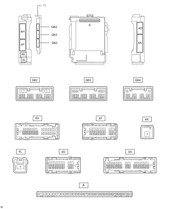
*1 Main Body ECU (Multiplex Network Body ECU) - -
-
Remove the main body ECU (multiplex network body ECU) from the junction block assembly LH.
-
Measure the voltage and resistance according to the value(s) in the table below.
Tester Connection Wiring Color Terminal Description Condition Specified Condition A-32 (IG) - Body ground None - Body ground Power source (IG) Engine switch off →on (IG) Below 1 V → 11 to 14 V A-30 (ACC) - Body ground None - Body ground Power source (ACC) Engine switch off →on (ACC) Below 1 V → 11 to 14 V A-31 (BECU) - Body ground None - Body ground Power source Always 11 to 14 V A-11 (GND1) - Body ground None - Body ground Ground Always Below 1 Ω -
Install the main body ECU (multiplex network body ECU) to the junction block assembly LH.
-
Measure the voltage according to the value(s) in the table below.
Terminal No.
(Symbol)
Wiring Color Terminal Description Condition Specified Condition G62-16 (SFTP) - Body ground R - Body ground P shift position switch signal Shift lever in P → shift lever not in P Below 1 V → 10.6 V
-