REAR POWER SEAT CONTROL SYSTEM(w/ Memory) Power Seat Position is not Memorized or does not Return to Memorized Position
DESCRIPTION
When the M1 switch, M2 switch or return switch of the rear power seat switch is pressed while the SET switch is being pressed, or when the M1 switch, M2 switch or return switch is pressed within 3 seconds of pressing the SET switch, the position control ECU assembly memorizes the position of the motors. When the M1 switch, M2 switch or return switch is pressed, the position control ECU assembly operates each motor based on the respective memorized position.
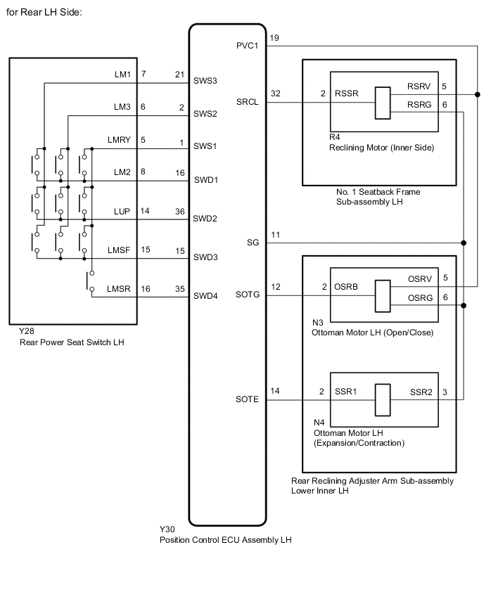
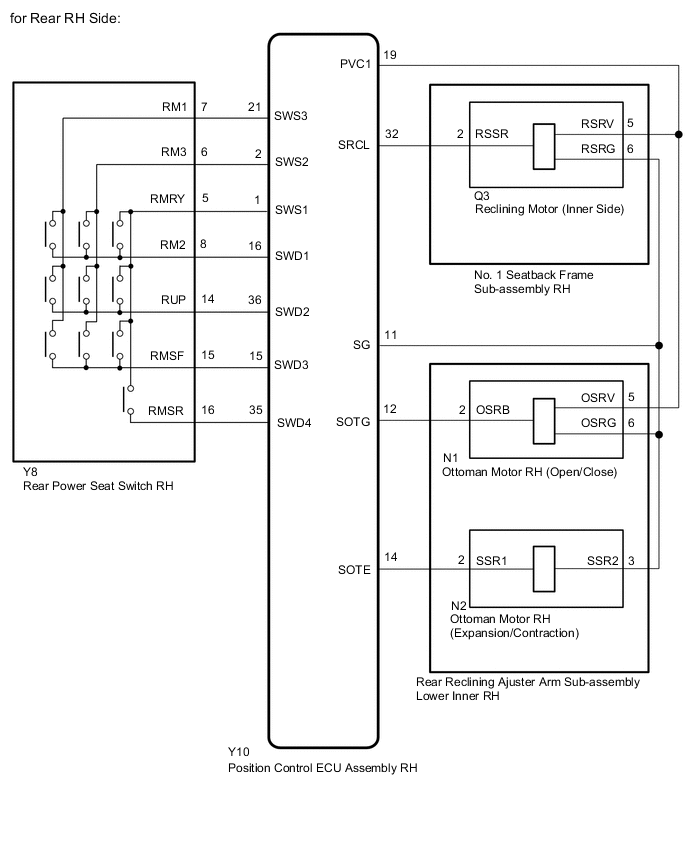
WIRING DIAGRAM
PROCEDURE
-
CHECK REAR POWER SEAT OPERATION
-
Check that each function of the power seat operates normally by using the rear power seat switch.
OK Each function of the power seat operates normally using the rear power seat switch. Result Proceed to OK NG
NG 
GO TO PROBLEM SYMPTOMS TABLE Click here
OK 
-
-
CHECK SEAT POSITION MEMORY AND RESTORING FUNCTION
-
Check that the seat position memory and restoring functions operate properly.
Result Result Proceed to Seat position memory and restoring functions do not operate properly (for Rear LH Side) A Seat position memory and restoring functions do not operate properly (for Rear RH Side) B
B 
CHECK SEAT POSITION MEMORY AND RESTORING FUNCTION Click here
A
-
-
CHECK SEAT POSITION MEMORY AND RESTORING FUNCTION
-
Check that the seat position memory and restoring functions operate properly.
Result Result Proceed to Seat position memory and restoring functions of both reclining and ottoman functions do not operate properly A Seat position memory and restoring functions of the reclining function do not operate properly B Seat position memory and restoring functions of the ottoman open/close function do not operate properly C Seat position memory and restoring functions of the ottoman expansion/contraction function do not operate properly D
B
CHECK HARNESS AND CONNECTOR (RECLINING MOTOR LH [Inner Side] - POSITION CONTROL ECU ASSEMBLY LH) Click here
C
CHECK HARNESS AND CONNECTOR (OTTOMAN MOTOR LH [Open/Close] - POSITION CONTROL ECU ASSEMBLY LH) Click here
D
CHECK HARNESS AND CONNECTOR (OTTOMAN MOTOR LH [Expansion/Contraction] - POSITION CONTROL ECU ASSEMBLY LH) Click here
A
-
-
INSPECT REAR POWER SEAT SWITCH LH
-
Remove the rear power seat switch LH.
-
Inspect the rear power seat switch LH.
Result Proceed to OK NG
NG
REPLACE REAR POWER SEAT SWITCH LH Click here
OK
-
-
CHECK HARNESS AND CONNECTOR (REAR POWER SEAT SWITCH LH - POSITION CONTROL ECU ASSEMBLY LH)
-
Disconnect the Y28 rear power seat switch LH connector.
-
Disconnect the Y30 position control ECU assembly LH connector.
-
Measure the resistance according to the value(s) in the table below.
Standard Resistance Tester Connection Condition Specified Condition Y28-7 (LM1) - Y30-21 (SWS3) Always Below 1 Ω Y28-7 (LM1) or Y30-21 (SWS3) - Body ground Always 10 kΩ or higher Y28-6 (LM3) - Y30-2 (SWS2) Always Below 1 Ω Y28-6 (LM3) or Y30-2 (SWS2) - Body ground Always 10 kΩ or higher Y28-5 (LMRY) - Y30-1 (SWS1) Always Below 1 Ω Y28-5 (LMRY) or Y30-1 (SWS1) - Body ground Always 10 kΩ or higher Y28-8 (LM2) - Y30-16 (SWD1) Always Below 1 Ω Y28-8 (LM2) or Y30-16 (SWD1) - Body ground Always 10 kΩ or higher Y28-14 (LUP) - Y30-36 (SWD2) Always Below 1 Ω Y28-14 (LUP) or Y30-36 (SWD2) - Body ground Always 10 kΩ or higher Y28-15 (LMSF) - Y30-15 (SWD3) Always Below 1 Ω Y28-15 (LMSF) or Y30-15 (SWD3) - Body ground Always 10 kΩ or higher Y28-16 (LMSR) - Y30-35 (SWD4) Always Below 1 Ω Y28-16 (LMSR) or Y30-35 (SWD4) - Body ground Always 10 kΩ or higher Result Proceed to OK NG
NG
REPAIR OR REPLACE HARNESS OR CONNECTOR
OK
-
-
CHECK HARNESS AND CONNECTOR (POSITION CONTROL ECU ASSEMBLY LH - RECLINING MOTOR LH [Inner Side])
-
Disconnect the Y30 position control ECU assembly LH connector.
-
Disconnect the R4 No. 1 seatback frame sub-assembly LH (reclining motor LH [inner side]) connector.
-
Measure the resistance according to the value(s) in the table below.
Standard Resistance Tester Connection Condition Specified Condition Y30-19 (PVC1) - R4-5 (RSRV) Always Below 1 Ω Y30-19 (PVC1) or R4-5 (RSRV) - Body ground Always 10 kΩ or higher Y30-11 (SG) - R4-6 (RSRG) Always Below 1 Ω Y30-11 (SG) or R4-6 (RSRG) - Body ground Always 10 kΩ or higher Result Proceed to OK NG
OK
REPLACE POSITION CONTROL ECU ASSEMBLY LH Click here
NG
REPAIR OR REPLACE HARNESS OR CONNECTOR
-
-
CHECK HARNESS AND CONNECTOR (RECLINING MOTOR LH [Inner Side] - POSITION CONTROL ECU ASSEMBLY LH)
-
Disconnect the R4 No. 1 seatback frame sub-assembly LH (riclining motor LH [inner Side]) connector.
-
Disconnect the Y30 position control ECU assembly LH connector.
-
Measure the resistance according to the value(s) in the table below.
Standard Resistance Tester Connection Condition Specified Condition R4-5 (RSRV) - Y30-19 (PVC1) Always Below 1 Ω R4-5 (RSRV) or Y30-19 (PVC1) - Body ground Always 10 kΩ or higher R4-2 (RSSR) - Y30-32 (SRCL) Always Below 1 Ω R4-2 (RSSR) or Y30-32 (SRCL) - Body ground Always 10 kΩ or higher R4-6 (RSRG) - Y30-11 (SG) Always Below 1 Ω R4-6 (RSRG) or Y30-11 (SG) - Body ground Always 10 kΩ or higher Result Proceed to OK NG
NG
REPAIR OR REPLACE HARNESS OR CONNECTOR
OK
-
-
CHECK POSITION CONTROL ECU ASSEMBLY LH
-
Reconnect the Y30 position control ECU assembly LH connector.

-
Measure the voltage according to the value(s) in the table below.
Standard Voltage Tester Connection Switch Condition Specified Condition Y30-19 (PVC1) - Y30-11 (SG) Reclining switch on 5 to 6.6 V Result Proceed to OK NG
NG
REPLACE POSITION CONTROL ECU ASSEMBLY LH Click here
OK
-
-
CHECK NO. 1 SEATBACK FRAME SUB-ASSEMBLY LH (RECLINING MOTOR LH [Inner Side])
-

*a Component with harness connected
(Reclining Motor LH [Inner Side])
Reconnect the No. 1 seatback frame sub-assembly LH (reclining motor LH [inner side]) connector.
-
Check for pulse according to the value(s) in the table below.
Standard Tester Connection Switch Condition Specified Condition R4-2 (RSSR) - Body ground Reclining switch on Pulse generation Result Proceed to OK NG
OK
REPLACE POSITION CONTROL ECU ASSEMBLY LH Click here
NG
REPLACE NO. 1 SEATBACK FRAME SUB-ASSEMBLY LH Click here
-
-
CHECK HARNESS AND CONNECTOR (OTTOMAN MOTOR LH [Open/Close] - POSITION CONTROL ECU ASSEMBLY LH)
-
Disconnect the N3 rear lower inner reclining adjuster arm sub-assembly LH (ottoman motor LH [open/close]) connector.
-
Disconnect the Y30 position control ECU assembly LH connector.
-
Measure the resistance according to the value(s) in the table below.
Standard Resistance Tester Connection Condition Specified Condition N3-5 (OSRV) - Y30-19 (PVC1) Always Below 1 Ω N3-5 (OSRV) or Y30-19 (PVC1) - Body ground Always 10 kΩ or higher N3-2 (OSRB) - Y30-12 (SOTG) Always Below 1 Ω N3-2 (OSRB) or Y30-12 (SOTG) - Body ground Always 10 kΩ or higher N3-6 (OSRG) - Y30-11 (SG) Always Below 1 Ω N3-6 (OSRG) or Y30-11 (SG) - Body ground Always 10 kΩ or higher Result Proceed to OK NG
NG
REPAIR OR REPLACE HARNESS OR CONNECTOR
OK
-
-
CHECK POSITION CONTROL ECU ASSEMBLY LH
-
Reconnect the Y30 position control ECU assembly LH connector.

-
Measure the voltage according to the value(s) in the table below.
Standard Voltage Tester Connection Switch Condition Specified Condition Y30-19 (PVC1) - Y30-11 (SG) Ottoman switch (open/close) on 5 to 6.6 V Result Proceed to OK NG
NG
REPLACE POSITION CONTROL ECU ASSEMBLY LH Click here
OK
-
-
CHECK REAR LOWER INNER RECLINING ADJUSTER ARM SUB-ASSEMBLY LH (OTTOMAN MOTOR LH [Open/Close])
-

*a Component with harness connected
(Ottoman Motor LH [Open/Close])
Reconnect the rear lower inner reclining adjuster arm sub-assembly LH (ottoman motor LH [open/close]) connector.
-
Check for pulse according to the value(s) in the table below.
Standard Tester Connection Switch Condition Specified Condition N3-2 (OSRB) - Body ground Ottoman switch (open/close) on Pulse generation Result Proceed to OK NG
OK
REPLACE POSITION CONTROL ECU ASSEMBLY LH Click here
NG
REPLACE REAR LOWER INNER RECLINING ADJUSTER ARM SUB-ASSEMBLY LH Click here
-
-
CHECK HARNESS AND CONNECTOR (OTTOMAN MOTOR LH [Expansion/Contraction] - POSITION CONTROL ECU ASSEMBLY LH)
-
Disconnect the N4 rear lower inner reclining adjuster arm sub-assembly LH (ottoman motor LH [expansion/contraction]) connector.
-
Disconnect the Y30 position control ECU assembly LH connector.
-
Measure the resistance according to the value(s) in the table below.
Standard Resistance Tester Connection Condition Specified Condition N4-2 (SSR1) - Y30-14 (SOTE) Always Below 1 Ω N4-2 (SSR1) or Y30-14 (SOTE) - Body ground Always 10 kΩ or higher N4-3 (SSR2) - Y30-11 (SG) Always Below 1 Ω N4-3 (SSR2) or Y30-11 (SG) - Body ground Always 10 kΩ or higher Result Proceed to OK NG
NG
REPAIR OR REPLACE HARNESS OR CONNECTOR
OK
-
-
CHECK POSITION CONTROL ECU ASSEMBLY LH
-
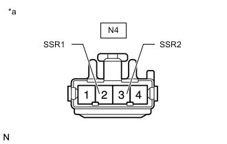
*a Front view of wire harness connector
(to Rear Lower Inner Reclining Adjuster Arm Sub-assembly LH)
Disconnect the N4 rear lower inner reclining adjuster arm sub-assembly LH (ottoman motor LH [expansion/contraction]) connector.
-
Measure the voltage according to the value(s) in the table below.
Standard Voltage Tester Connection Switch Condition Specified Condition N4-2 (SSR1) - N4-3 (SSR2) Ottoman switch (expansion/contraction) on 4.8 to 5.1 V Result Proceed to OK NG
NG
REPLACE POSITION CONTROL ECU ASSEMBLY LH Click here
OK
-
-
CHECK REAR RECLINING ADJUSTER ARM SUB-ASSEMBLY LOWER INNER LH (OTTOMAN MOTOR LH [Expansion/Contraction])
-
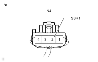
*a Component with harness connected
(Ottoman Motor LH [Expansion/Contraction])
Reconnect the rear lower inner reclining adjuster arm sub-assembly LH (ottoman motor LH [expansion/contraction]) connector.
-
Check for pulse according to the value(s) in the table below.
Standard Tester Connection Switch Condition Specified Condition N4-2 (SSR1) - Body ground Ottoman switch (expansion/contraction) on Pulse generation Result Proceed to OK NG
OK
REPLACE POSITION CONTROL ECU ASSEMBLY LH Click here
NG
REPLACE REAR LOWER INNER RECLINING ADJUSTER ARM SUB-ASSEMBLY LH Click here
-
-
CHECK SEAT POSITION MEMORY AND RESTORING FUNCTION
-
Check that the seat position memory and restoring functions operate properly.
Result Result Proceed to Seat position memory and restoring functions of both reclining and ottoman functions do not operate properly A Seat position memory and restoring functions of the reclining function do not operate properly B Seat position memory and restoring functions of the ottoman open/close function do not operate properly C Seat position memory and restoring functions of the ottoman expansion/contraction function do not operate properly D
B
CHECK HARNESS AND CONNECTOR (RECLINING MOTOR RH [Inner Side] - POSITION CONTROL ECU ASSEMBLY RH) Click here
C
CHECK HARNESS AND CONNECTOR (OTTOMAN MOTOR RH [Open/Close] - POSITION CONTROL ECU ASSEMBLY RH) Click here
D
CHECK HARNESS AND CONNECTOR (OTTOMAN MOTOR RH [Expansion/Contraction] - POSITION CONTROL ECU ASSEMBLY RH) Click here
A
-
-
INSPECT REAR POWER SEAT SWITCH RH
-
Remove the rear power seat switch RH.
-
Inspect the rear power seat switch RH.
Result Proceed to OK NG
NG
REPLACE REAR POWER SEAT SWITCH RH Click here
OK
-
-
CHECK HARNESS AND CONNECTOR (REAR POWER SEAT SWITCH RH - POSITION CONTROL ECU ASSEMBLY RH)
-
Disconnect the Y8 rear power seat switch RH connector.
-
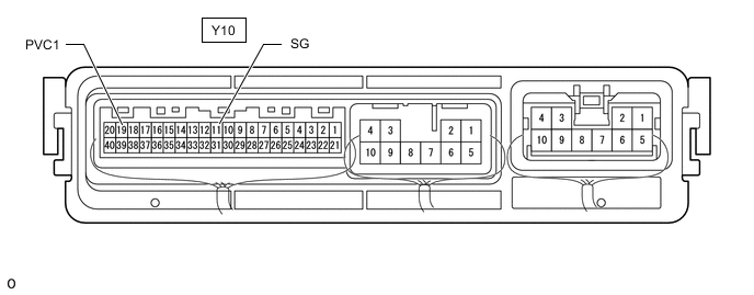
Disconnect the Y10 position control ECU assembly RH connector.
-
Measure the resistance according to the value(s) in the table below.
Standard Resistance Tester Connection Condition Specified Condition Y8-7 (RM1) - Y10-21 (SWS3) Always Below 1 Ω Y8-7 (RM1) or Y10-21 (SWS3) - Body ground Always 10 kΩ or higher Y8-6 (RM3) - Y10-2 (SWS2) Always Below 1 Ω Y8-6 (RM3) or Y10-2 (SWS2) - Body ground Always 10 kΩ or higher Y8-5 (RMRY) - Y10-1 (SWS1) Always Below 1 Ω Y8-5 (RMRY) or Y10-1 (SWS1) - Body ground Always 10 kΩ or higher Y8-8 (RM2) - Y10-16 (SWD1) Always Below 1 Ω Y8-8 (RM2) or Y10-16 (SWD1) - Body ground Always 10 kΩ or higher Y8-14 (RUP) - Y10-36 (SWD2) Always Below 1 Ω Y8-14 (RUP) or Y10-36 (SWD2) - Body ground Always 10 kΩ or higher Y8-15 (RMSF) - Y10-15 (SWD3) Always Below 1 Ω Y8-15 (RMSF) or Y10-15 (SWD3) - Body ground Always 10 kΩ or higher Y8-16 (RMSR) - Y10-35 (SWD4) Always Below 1 Ω Y8-16 (RMSR) or Y10-35 (SWD4) - Body ground Always 10 kΩ or higher Result Proceed to OK NG
NG
REPAIR OR REPLACE HARNESS OR CONNECTOR
OK
-
-
CHECK HARNESS AND CONNECTOR (POSITION CONTROL ECU ASSEMBLY RH - RECLINING MOTOR RH [Inner Side])
-
Disconnect the Y10 position control ECU assembly RH connector.
-
Disconnect the Q3 No. 1 seatback frame sub-assembly RH (reclining motor RH [inner side]) connector.
-
Measure the resistance according to the value(s) in the table below.
Standard Resistance Tester Connection Condition Specified Condition Y10-19 (PVC1) - Q3-5 (RSRV) Always Below 1 Ω Y10-19 (PVC1) or Q3-5 (RSRV) - Body ground Always 10 kΩ or higher Y10-11 (SG) - Q3-6 (RSRG) Always Below 1 Ω Y10-11 (SG) or Q3-6 (RSRG) - Body ground Always 10 kΩ or higher Result Proceed to OK NG
OK
REPLACE POSITION CONTROL ECU ASSEMBLY RH Click here
NG
REPAIR OR REPLACE HARNESS OR CONNECTOR
-
-
CHECK HARNESS AND CONNECTOR (RECLINING MOTOR RH [Inner Side] - POSITION CONTROL ECU ASSEMBLY RH)
-
Disconnect the Q3 No. 1 seatback frame sub-assembly RH (reclining motor RH [inner side]) connector.
-
Disconnect the Y10 position control ECU assembly RH connector.
-
Measure the resistance according to the value(s) in the table below.
Standard Resistance Tester Connection Condition Specified Condition Q3-5 (RSRV) - Y10-19 (PVC1) Always Below 1 Ω Q3-5 (RSRV) or Y10-19 (PVC1) - Body ground Always 10 kΩ or higher Q3-2 (RSSR) - Y10-32 (SRCL) Always Below 1 Ω Q3-2 (RSSR) or Y10-32 (SRCL) - Body ground Always 10 kΩ or higher Q3-6 (RSRG) - Y10-11 (SG) Always Below 1 Ω Q3-6 (RSRG) or Y10-11 (SG) - Body ground Always 10 kΩ or higher Result Proceed to OK NG
NG
REPAIR OR REPLACE HARNESS OR CONNECTOR
OK
-
-
CHECK POSITION CONTROL ECU ASSEMBLY RH
-
Reconnect the Y10 position control ECU assembly RH connector.

-
Measure the voltage according to the value(s) in the table below.
Standard Voltage Tester Connection Switch Condition Specified Condition Y10-19 (PVC1) - Y10-11 (SG) Reclining switch on 5 to 6.6 V Result Proceed to OK NG
NG
REPLACE POSITION CONTROL ECU ASSEMBLY RH Click here
OK
-
-
CHECK NO. 1 SEATBACK FRAME SUB-ASSEMBLY RH (RECLINING MOTOR RH [Inner Side])
-
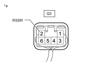
*a Component with harness connected
(Reclining Motor RH [Inner Side])
Reconnect the No. 1 seatback frame sub-assembly RH (reclining motor RH [inner side]) connector.
-
Check for pulse according to the value(s) in the table below.
Standard Tester Connection Switch Condition Specified Condition Q3-2 (RSSR) - Body ground Reclining switch on Pulse generation Result Proceed to OK NG
OK
REPLACE POSITION CONTROL ECU ASSEMBLY RH Click here
NG
REPLACE NO.1 SEAT BACK FRAME SUB-ASSEMBLY RH Click here
-
-
CHECK HARNESS AND CONNECTOR (OTTOMAN MOTOR RH [Open/Close] - POSITION CONTROL ECU ASSEMBLY RH)
-
Disconnect the N1 rear lower inner reclining adjuster arm sub-assembly RH (ottoman motor RH [open/close]) connector.
-
Disconnect the Y10 position control ECU assembly RH connector.
-
Measure the resistance according to the value(s) in the table below.
Standard Resistance Tester Connection Condition Specified Condition N1-5 (OSRV) - Y10-19 (PVC1) Always Below 1 Ω N1-5 (OSRV) or Y10-19 (PVC1) - Body ground Always 10 kΩ or higher N1-2 (OSRB) - Y10-12 (SOTG) Always Below 1 Ω N1-2 (OSRB) or Y10-12 (SOTG) - Body ground Always 10 kΩ or higher N1-6 (OSRG) - Y10-11 (SG) Always Below 1 Ω N1-6 (OSRG) or Y10-11 (SG) - Body ground Always 10 kΩ or higher Result Proceed to OK NG
NG
REPAIR OR REPLACE HARNESS OR CONNECTOR
OK
-
-
CHECK POSITION CONTROL ECU ASSEMBLY RH
-
Reconnect the Y10 position control ECU assembly RH connector.
-
Measure the voltage according to the value(s) in the table below.
Standard Voltage Tester Connection Switch Condition Specified Condition Y10-19 (PVC1) - Y10-11 (SG) Ottoman switch (open/close) on 5 to 6.6 V Result Proceed to OK NG
NG
REPLACE POSITION CONTROL ECU ASSEMBLY RH Click here
OK
-
-
CHECK REAR LOWER INNER RECLINING ADJUSTER ARM SUB-ASSEMBLY LH (OTTOMAN MOTOR RH [Open/Close])
-
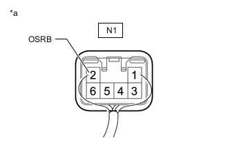
*a Component with harness connected
(Ottoman Motor RH [Open/Close])
Reconnect the rear lower inner reclining adjuster arm sub-assembly RH (ottoman motor RH [open/close]) connector.
-
Check for pulse according to the value(s) in the table below.
Standard Tester Connection Switch Condition Specified Condition N1-2 (OSRB) - Body ground Ottoman switch (open/close) on Pulse generation Result Proceed to OK NG
OK
REPLACE POSITION CONTROL ECU ASSEMBLY RH Click here
NG
REPLACE REAR LOWER INNER RECLINING ADJUSTER ARM SUB-ASSEMBLY RH Click here
-
-
CHECK HARNESS AND CONNECTOR (OTTOMAN MOTOR RH [Expansion/Contraction] - POSITION CONTROL ECU ASSEMBLY RH)
-
Disconnect the N2 rear lower inner reclining adjuster arm sub-assembly RH (ottoman motor RH [expansion/contraction]) connector.
-
Disconnect the Y10 position control ECU assembly RH connector.
-
Measure the resistance according to the value(s) in the table below.
Standard Resistance Tester Connection Condition Specified Condition N2-2 (SSR1) - Y10-14 (SOTE) Always Below 1 Ω N2-2 (SSR1) or Y10-14 (SOTE) - Body ground Always 10 kΩ or higher N2-3 (SSR2) - Y10-11 (SG) Always Below 1 Ω N2-3 (SSR2) or Y10-11 (SG) - Body ground Always 10 kΩ or higher Result Proceed to OK NG
NG
REPAIR OR REPLACE HARNESS OR CONNECTOR
OK
-
-
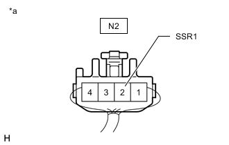
CHECK POSITION CONTROL ECU ASSEMBLY RH
-
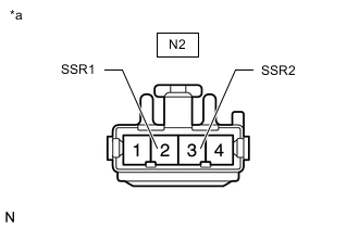
*a Front view of wire harness connector
(to Rear Lower Inner Reclining Adjuster Arm Sub-assembly RH)
Disconnect the N2 rear lower inner reclining adjuster arm sub-assembly RH (ottoman motor RH [expansion/contraction]) connector.
-
Measure the voltage according to the value(s) in the table below.
Standard Voltage Tester Connection Switch Condition Specified Condition N2-2 (SSR1) - N4-3 (SSR2) Ottoman switch (expansion/contraction) on 4.8 to 5.1 V Result Proceed to OK NG
NG
REPLACE POSITION CONTROL ECU ASSEMBLY RH Click here
OK
-
-
CHECK REAR LOWER INNER RECLINING ADJUSTER ARM SUB-ASSEMBLY RH (OTTOMAN MOTOR RH [Expansion/Contraction])
-
*a Component with harness connected
(Ottoman Motor RH [Expansion/Contraction])
Reconnect the rear lower inner reclining adjuster arm sub-assembly RH (ottoman motor RH [expansion/contraction]) connector.
-
Check for pulse according to the value(s) in the table below.
Standard Tester Connection Switch Condition Specified Condition N2-2 (SSR1) - Body ground Ottoman switch (expansion/contraction) on Pulse generation Result Proceed to OK NG
OK
REPLACE POSITION CONTROL ECU ASSEMBLY RH Click here
NG
REPLACE REAR LOWER INNER RECLINING ADJUSTER ARM SUB-ASSEMBLY RH Click here
-