FRONT POWER SEAT CONTROL SYSTEM Front Power Seat does not Operate with Front Power Seat Switch
DESCRIPTION
Signals are input into the front power seat switch LH*1 or RH*2. The built-in ECU manages the signals received from the front power seat switch LH*1 or RH*2, and operates each motor. If the front power seat switch LH*1 or RH*2 receives more than 2 motor operation signals, the motor is stopped. Manual operation is restarted after the front power seat switch LH*1 or RH*2 receives 1 signal only.
-
*1: for LHD
-
*2: for RHD
WIRING DIAGRAM
Figure 1. for LHD
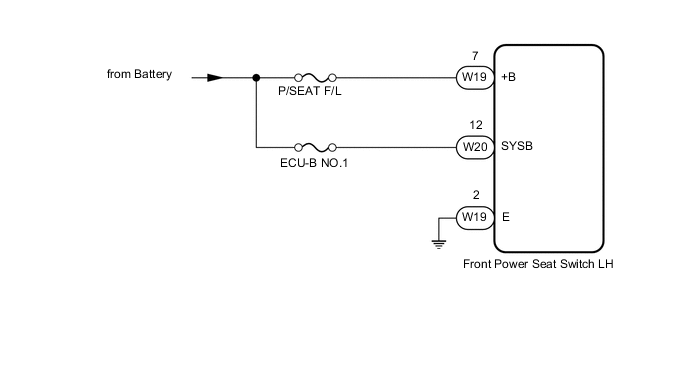
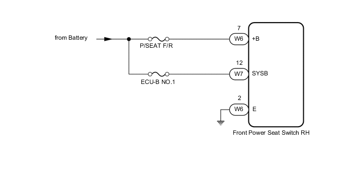
Figure 2. for RHD
CAUTION / NOTICE / HINT
Tech Tips
Inspect the fuses for circuits related to this system before performing the following procedure.
PROCEDURE
-
CHECK FRONT POWER SEAT OPERATION
-
*1: for LHD
-
*2: for RHD
-
Check that each function of the power seat operates normally by using the front power seat switch LH*1 or RH*2.
Result Result Proceed to All power seat functions do not operate A One or more power seat functions do not operate B
B 
GO TO OTHER DIAGNOSIS PROCEDURE (One or more Power Seat Motors do not Operate) Click here
A 
-
-
CHECK HARNESS AND CONNECTOR (FRONT POWER SEAT SWITCH - BATTERY AND BODY GROUND)
-
*1: for LHD
-
*2: for RHD
-
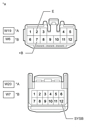
*A for LHD *B for RHD *a Front view of wire harness connector
(to Front Power Seat Switch)
Disconnect the front power seat switch LH*1 or RH*2 connectors.
-
Measure the resistance according to the value(s) in the table below.
Standard Resistance for LHD Tester Connection Condition Specified Condition W19-2 (E) - Body ground Always Below 1 Ω for RHD Tester Connection Condition Specified Condition W6-2 (E) - Body ground Always Below 1 Ω -
Measure the voltage according to the value(s) in the table below.
Standard Voltage for LHD Tester Connection Condition Specified Condition W19-7 (+B) - Body ground Always 11 to 14 V W20-12 (SYSB) - Body ground Always 11 to 14 V for RHD Tester Connection Condition Specified Condition W6-7 (+B) - Body ground Always 11 to 14 V W7-12 (SYSB) - Body ground Always 11 to 14 V Result Proceed to OK NG
OK
REPLACE FRONT POWER SEAT SWITCH Click here
NG
REPAIR OR REPLACE HARNESS OR CONNECTOR
-