FRONT POWER SEAT CONTROL SYSTEM TERMINALS OF ECU
-
CHECK FRONT POWER SEAT SWITCH LH (for LHD)

-
Disconnect the W19 and W20 front power seat switch LH connectors.
-
Measure the voltage and resistance according to the value(s) in the table below.
Tester Connection Wiring Color Terminal Description Condition Specified Condition W19-2 (E) - Body ground W-B - Body ground Ground Always Below 1 Ω W19-7 (+B) - Body ground W - Body ground Battery power supply Always 11 to 14 V W20-12 (SYSB) - Body ground P - Body ground System power source Always 11 to 14 V -
Reconnect the W19 and W20 front power seat switch LH connectors.
-
Measure the voltage and resistance to the value(s) in the table below.
-
Check for pulses according to the value(s) in the table below.
Tester Connection Wiring Color Terminal Description Condition Specified Condition W19-3 (SLD+) - Body ground L - Body ground Slide motor signal (forward) Slide switch off Below 1 V Slide switch on (Forward) 11 to 14 V W19-4 (SLD-) - Body ground GR - Body ground Slide motor signal (rearward) Slide switch off Below 1 V Slide switch on (Rearward) 11 to 14 V W19-5 (FRV-) - Body ground R - Body ground Front vertical motor signal (downward) Front vertical switch off Below 1 V Front vertical switch on (Downward) 11 to 14 V W19-8 (FRV+) - Body ground B - Body ground Front vertical motor signal (upward) Front vertical switch off Below 1 V Front vertical switch on (Upward) 11 to 14 V W19-9 (RCL+) - Body ground P - Body ground Reclining motor signal (forward) Reclining switch off Below 1 V Reclining switch on (Forward) 11 to 14 V W19-11 (RCL-) - Body ground LG - Body ground Reclining motor signal (rearward) Reclining switch off Below 1 V Reclining switch on (Rearward) 11 to 14 V W19-10 (LFT+) - Body ground V - Body ground Rear lifter motor signal (upward) Rear lifter switch off Below 1 V Rear lifter switch on (Upward) 11 to 14 V W19-12 (LFT-) - Body ground G - Body ground Rear lifter motor signal (downward) Rear lifter switch off Below 1 V Rear lifter switch on (Downward) 11 to 14 V W20-1 (SGND) - Body ground BR - Body ground Position sensor ground Always Below 1 Ω W20-3 (SSFV) - Body ground R - Body ground Front vertical position signal Front vertical function operating Pulse generation W20-4 (SSRL) - Body ground P - Body ground Rear lifter position signal Rear lifter function operating Pulse generation W20-5 (SSRS) - Body ground G - Body ground Slide position signal Slide function operating Pulse generation W20-11 (SSRR) - Body ground V - Body ground Reclining position signal Reclining function operating Pulse generation W20-10 (DBCL) - Body ground GR - Body ground Driver seat inner belt signal Engine switch off, front seat operated, driver seat outer belt not fastened → fastened 11 to 14 V → Below 1 V
-
-
CHECK FRONT POWER SEAT SWITCH RH (for RHD)

-
Disconnect the W6 and W7 front power seat switch RH connectors.
-
Measure the voltage and resistance according to the value(s) in the table below.
Tester Connection Wiring Color Terminal Description Condition Specified Condition W6-2 (E) - Body ground W-B - Body ground Ground Always Below 1 Ω W6-7 (+B) - Body ground W - Body ground Battery power supply Always 11 to 14 V W7-12 (SYSB) - Body ground P - Body ground System power source Always 11 to 14 V -
Reconnect the W6 and W7 front power seat switch RH connectors.
-
Measure the voltage and resistance according to the value(s) in the table below.
-
Check for pulses according to the value(s) in the table below.
Tester Connection Wiring Color Terminal Description Condition Specified Condition W6-3 (SLD+) - Body ground L - Body ground Slide motor signal (forward) Slide switch off Below 1 V Slide switch on (Forward) 11 to 14 V W6-4 (SLD-) - Body ground GR - Body ground Slide motor signal (rearward) Slide switch off Below 1 V Slide switch on (Rearward) 11 to 14 V W6-5 (FRV-) - Body ground R - Body ground Front vertical motor signal (downward) Front vertical switch off Below 1 V Front vertical switch on (Downward) 11 to 14 V W6-8 (FRV+) - Body ground B - Body ground Front vertical motor signal (upward) Front vertical switch off Below 1 V Front vertical switch on (Upward) 11 to 14 V W6-9 (RCL+) - Body ground P - Body ground Reclining motor signal (forward) Reclining switch off Below 1 V Reclining switch on (Forward) 11 to 14 V W6-11 (RCL-) - Body ground LG - Body ground Reclining motor signal (rearward) Reclining switch off Below 1 V Reclining switch on (Rearward) 11 to 14 V W6-10 (LFT+) - Body ground V - Body ground Rear lifter motor signal (upward) Rear lifter switch off Below 1 V Rear lifter switch on (Upward) 11 to 14 V W6-12 (LFT-) - Body ground G - Body ground Rear lifter motor signal (downward) Rear lifter switch off Below 1 V Rear lifter switch on (Downward) 11 to 14 V W7-1 (SGND) - Body ground BR - Body ground Position sensor ground Always Below 1 Ω W7-3 (SSFV) - Body ground R - Body ground Front vertical position signal Front vertical function operating Pulse generation W7-4 (SSRL) - Body ground P - Body ground Rear lifter position signal Rear lifter function operating Pulse generation W7-5 (SSRS) - Body ground G - Body ground Slide position signal Slide function operating Pulse generation W7-11 (SSRR) - Body ground V - Body ground Reclining position signal Reclining function operating Pulse generation W7-10 (DBCL) - Body ground GR - Body ground Driver seat inner belt signal Engine switch off, front seat operated, driver seat outer belt not fastened → fastened 11 to 14 V → Below 1 V
-
-
CHECK OUTER MIRROR CONTROL ECU ASSEMBLY LH (for LHD)

-
Disconnect the I28 outer mirror control ECU assembly LH connector.
-
Measure the voltage and resistance according to the value(s) in the table below.
Tester Connection Wiring Color Terminal Description Condition Specified Condition I28-5 (SIG) - Body ground B - Body ground IG power supply Engine switch off Below 1 V Engine switch on (IG) 11 to 14 V I28-6 (CPUB) - Body ground R - Body ground Battery power supply Always 11 to 14 V I28-7 (GND) - Body ground W-B - Body ground Ground Always Below 1 Ω I28-14 (BDR) - Body ground B - Body ground Battery power supply Always 11 to 14 V -
Reconnect the I28 outer mirror control ECU assrmbly LH connector.
-
Measure the voltage according to the value(s) in the table below.
Tester Connection Wiring Color Terminal Description Condition Specified Condition I28-1 (MM) - Body ground W - Body ground SET switch signal for seat memory switch SET switch on Below 1 V SET switch off 11 to 14 V I28-2 (M1) - Body ground B - Body ground M1 switch signal for seat memory switch M1 switch on Below 1 V M1 switch off 11 to 14 V I28-3 (M2) - Body ground LG - Body ground M2 switch signal for seat memory switch M2 switch on Below 1 V M2 switch off 11 to 14 V I28-4 (M3) - Body ground V - Body ground M3 switch signal for seat memory switch M3 switch on Below 1 V M3 switch off 11 to 14 V
-
-
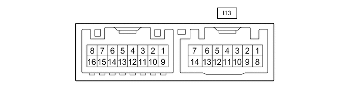
CHECK OUTER MIRROR CONTROL ECU ASSEMBLY RH (for RHD)
-
Disconnect the I13 outer mirror control ECU assembly RH connector.
-
Measure the voltage and resistance according to the value(s) in the table below.
Tester Connection Wiring Color Terminal Description Condition Specified Condition I13-5 (SIG) - Body ground B - Body ground IG power supply Engine switch off Below 1 V Engine switch on (IG) 11 to 14 V I13-6 (CPUB) - Body ground R - Body ground Battery power supply Always 11 to 14 V I13-7 (GND) - Body ground W-B - Body ground Ground Always Below 1 Ω I13-14 (BDR) - Body ground B - Body ground Battery power supply Always 11 to 14 V -
Reconnect the I13 outer mirror control ECU assembly RH connector.
-
Measure the voltage according to the value(s) in the table below.
Tester Connection Wiring Color Terminal Description Condition Specified Condition I13-1 (MM) - Body ground W - Body ground SET switch signal for seat memory switch SET switch on Below 1 V SET switch off 11 to 14 V I13-2 (M1) - Body ground R - Body ground M1 switch signal for seat memory switch M1 switch on Below 1 V M1 switch off 11 to 14 V I13-3 (M2) - Body ground LG - Body ground M2 switch signal for seat memory switch M2 switch on Below 1 V M2 switch off 11 to 14 V I13-4 (M3) - Body ground V - Body ground M3 switch signal for seat memory switch M3 switch on Below 1 V M3 switch off 11 to 14 V
-