CENTER AIRBAG SENSOR ASSEMBLY(w/ Navigation System) INSTALLATION
PROCEDURE
-
INSTALL AIRBAG ECU ASSEMBLY
-
Check that the engine switch is off.
-
Check that the cable is disconnected from the negative (-) battery terminal.
CAUTION:
-
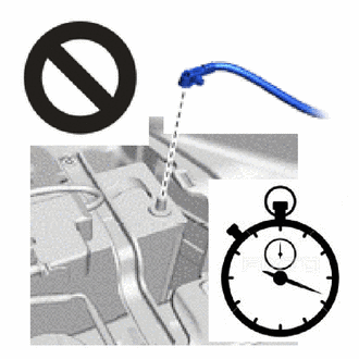
Wait at least 90 seconds after disconnecting the cable from the negative (-) battery terminal to disable the SRS system.
-
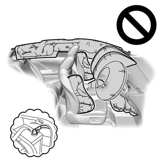
If this procedure is performed without disconnecting the negative (-) terminal of the battery, the airbag may deploy even if an impact is applied only to the airbag ECU assembly. Therefore, make sure that the negative (-) terminal of the battery is disconnected before performing this procedure.
-
-
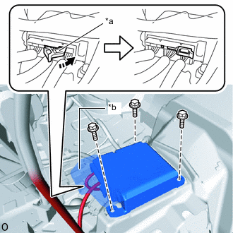
*a Connector Lock *b Waterproof Sheet 
Lock Direction Check that the waterproof sheet is properly set.
-
Install the airbag ECU assembly with the 3 bolts.
- Torque:
- 17.5 N*m { 178 kgf*cm, 13 ft.*lbf }
Note
-
If the airbag ECU assembly has been dropped, or there are any cracks, dents or other defects in the case or connector, replace the airbag ECU assembly with a new one.
-
When installing the airbag ECU assembly, be careful that the SRS wiring does not interfere with or is not pinched between other parts.
-
When the engine switch is first turned on (IG) after the airbag ECU assembly has been replaced, make sure that no one is in the vehicle.
-
Connect the airbag connector and push the connector lock to lock the airbag connector.
Note
-
When connecting any airbag connector, take care not to damage the airbag wire harness.
-
Do not allow the water proof sheet to become pinched.
-
-
Check that there is no looseness in the installation parts of the airbag ECU assembly.
-
-
INSTALL STEREO COMPONENT AMPLIFIER ASSEMBLY
-
INSTALL REAR NO. 1 AIR DUCT
for LHD:
for RHD:
-
INSTALL REAR NO. 2 AIR DUCT
for LHD:
for RHD:
-
INSTALL REAR NO. 4 AIR DUCT
for LHD:
for RHD:
-
INSTALL REAR NO. 3 AIR DUCT
for LHD:
for RHD:
-
INSTALL REAR NO. 5 AIR DUCT
for LHD:
for RHD:
-
INSTALL FRONT FLOOR SIDE PAD LH
for LHD:
for RHD:
-
INSTALL FRONT FLOOR SIDE PAD RH
for LHD:
for RHD:
-
INSTALL FRONT FLOOR CARPET ASSEMBLY
for LHD:
for RHD:
-
INSTALL INSTRUMENT PANEL SAFETY PAD
for LHD:
for RHD:
-
INSTALL LOWER CENTER PILLAR GARNISH LH
-
INSTALL LOWER CENTER PILLAR GARNISH RH
-
INSTALL LAP BELT OUTER ANCHOR COVER
-
INSTALL NO. 2 ASSIST GRIP
-
INSTALL NO. 1 ASSIST GRIP
-
INSTALL ASSIST GRIP PLUG
-
INSTALL ASSIST GRIP PLUG
-
INSTALL REAR DOOR SCUFF PLATE LH
-
INSTALL REAR DOOR SCUFF PLATE RH
-
INSTALL FRONT SEAT ASSEMBLY
for Manual Seat:
for Power Seat LH Side:
for Power Seat LH Side:
-
INSTALL DOOR SCUFF PLATE ASSEMBLY LH
-
INSTALL COWL SIDE TRIM BOARD LH
-
INSTALL DOOR SCUFF PLATE ASSEMBLY RH
-
INSTALL COWL SIDE TRIM BOARD RH
-
CONNECT CABLE TO NEGATIVE BATTERY TERMINAL
Note
When disconnecting the cable, some systems need to be initialized after the cable is reconnected.
-
PERFORM DIAGNOSTIC SYSTEM CHECK
-
CHECK SRS WARNING LIGHT