CENTER AIRBAG SENSOR ASSEMBLY(w/ Navigation System) REMOVAL
CAUTION / NOTICE / HINT
The necessary procedures (adjustment, calibration, initialization or registration) that must be performed after parts are installed, removed or replaced during the airbag ECU assembly removal/installation are shown below.
| Replacement Part or Procedure | Necessary Procedures | Effects/Inoperative Functions when not Performed | Link |
|---|---|---|---|
| Disconnect cable from negative (-) battery terminal | Drive the vehicle until stop and start control is permitted (approximately 15 to 40 minutes) | Stop and start system | |
| Correct the steering angle neutral point | Panoramic view monitor system | ||
| Servo motor initialization | Air conditioning system | ||
| Reset slide door close position | Power slide door system | ||
| Reset back door close position | Back door opener | ||
| Initialize back door lock | Power door lock control system | ||
| Replace airbag ECU assembly |
|
Brake control / Dynamic control systems |
Tech Tips
-
Use the same procedure for RHD and LHD vehicles.
-
The procedures listed below are for LHD vehicles.
PROCEDURE
-
PRECAUTION
Note
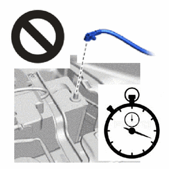
After turning the engine switch off, waiting time may be required before disconnecting the cable from the negative (-) battery terminal. Therefore, make sure to read the disconnecting the cable from the negative (-) battery terminal notice before proceeding with work.
-
DISCONNECT CABLE FROM NEGATIVE BATTERY TERMINAL
CAUTION:
-
Wait at least 90 seconds after disconnecting the cable from the negative (-) battery terminal to disable the SRS system.
-
If the airbag deploys for any reason, it may cause a serious accident.
Note
When disconnecting the cable, some systems need to be initialized after the cable is reconnected.
-
-
REMOVE COWL SIDE TRIM BOARD LH
-
REMOVE DOOR SCUFF PLATE ASSEMBLY LH
-
REMOVE COWL SIDE TRIM BOARD RH
-
REMOVE DOOR SCUFF PLATE ASSEMBLY RH
-
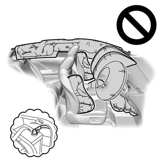
REMOVE FRONT SEAT ASSEMBLY
for Manual Seat:
for Power Seat LH Side:
for Power Seat RH Side:
for Super Long Slide Seat:
-
REMOVE REAR DOOR SCUFF PLATE LH
-
REMOVE REAR DOOR SCUFF PLATE RH
-
REMOVE ASSIST GRIP PLUG
-
REMOVE ASSIST GRIP PLUG
-
REMOVE NO. 1 ASSIST GRIP
-
REMOVE NO. 2 ASSIST GRIP
-
REMOVE LAP BELT OUTER ANCHOR COVER
-
REMOVE LOWER CENTER PILLAR GARNISH LH
-
REMOVE LOWER CENTER PILLAR GARNISH RH
-
REMOVE REAR NO. 1 SEAT ASSEMBLY LH (for Super Long Slide Seat)
-
REMOVE REAR NO. 2 SEAT ASSEMBLY LH (for Super Long Slide Seat)
-
REMOVE NO. 3 FLOOR CARPET MOULDING (for Super Long Slide Seat)
-
REMOVE REAR SEAT LOCK STRIKER COVER (for Super Long Slide Seat)
-
REMOVE LOWER NO. 1 SEAT TRACK RAIL PROTECTOR (for Super Long Slide Seat)
-
REMOVE LOWER NO. 2 SEAT TRACK RAIL PROTECTOR (for Super Long Slide Seat)
-
REMOVE LOWER NO. 3 SEAT TRACK RAIL PROTECTOR (for Super Long Slide Seat)
-
REMOVE HEATER AIR OUTLET GRILLE (for Super Long Slide Seat)
-
REMOVE REAR DOOR SCUFF PLATE LH
-
REMOVE REAR DOOR SCUFF PLATE RH
-
REMOVE INSTRUMENT PANEL SAFETY PAD
for LHD:
for RHD:
-
REMOVE FRONT FLOOR CARPET ASSEMBLY
for LHD:
for RHD:
-
REMOVE FRONT FLOOR SIDE PAD LH
for LHD:
for RHD:
-
REMOVE FRONT FLOOR SIDE PAD RH
for LHD:
for RHD:
-
REMOVE REAR NO. 5 AIR DUCT
for LHD:
for RHD:
-
REMOVE REAR NO. 3 AIR DUCT
for LHD:
for RHD:
-
REMOVE REAR NO. 4 AIR DUCT
for LHD:
for RHD:
-
REMOVE REAR NO. 2 AIR DUCT
for LHD:
for RHD:
-
REMOVE REAR NO. 1 AIR DUCT
for LHD:
for RHD:
-
REMOVE STEREO COMPONENT AMPLIFIER ASSEMBLY
-
REMOVE AIRBAG ECU ASSEMBLY
-
Check that the engine switch is off.
-
Check that the cable is disconnected from the negative (-) battery terminal.
CAUTION:
-
Wait at least 90 seconds after disconnecting the cable from the negative (-) battery terminal to disable the SRS system.
-
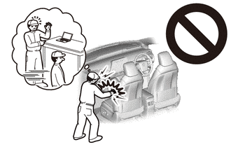
If this procedure is performed without disconnecting the negative (-) terminal of the battery, the airbag may deploy even if an impact is applied only to the airbag ECU assembly. Therefore, make sure that the negative (-) terminal of the battery is disconnected before performing this procedure.
-
-
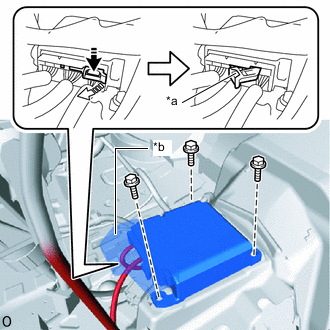
*a Connector Lock Lever *b Waterproof Sheet 
Push in this Direction 
Release in this Direction Disconnect the airbag connector.
Note
-
When disconnecting any airbag connector, take care not to damage the airbag wire harness.
-
Do not remove the waterproof sheet.
-
Push and pull the connector lock lever to release the connector lock as shown in the illustration.
-
Disconnect the airbag connector.
-
-
Remove the 3 bolts and airbag ECU assembly.
Note
If the airbag ECU assembly has been dropped, or there are any cracks, dents or other defects in the case or connector, replace the airbag ECU assembly with a new one.
-