KNEE AIRBAG ASSEMBLY INSTALLATION

CAUTION / NOTICE / HINT
Tech Tips
-
Use the same procedure for RHD and LHD vehicles.
-
The procedure listed below is for LHD vehicles.
PROCEDURE
-
INSTALL LOWER NO. 1 INSTRUMENT PANEL AIRBAG ASSEMBLY
-
Check that the engine switch is off.
-
Check that the cable is disconnected from the negative (-) battery terminal.
CAUTION:
-
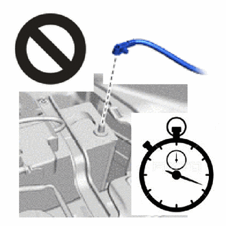
Wait at least 90 seconds after disconnecting the cable from the negative (-) battery terminal to disable the SRS system.
-
If the airbag deploys for any reason, it may cause a serious accident.
-
-
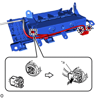
*a Connector Lock 
Push in this Direction Connect the airbag connector and push in the connector lock.
Note
When connecting any airbag connector, take care not to damage the airbag wire harness.
-
Attach the wire harness clamp.
-
Attach the claw to connect the DLC3.
-
Attach the claw to set the lower No. 1 instrument panel airbag assembly.
-
Install the 4 bolts.
- Torque:
- 10 N*m { 102 kgf*cm, 7 ft.*lbf }
Note
Confirm that the lower No. 1 instrument panel airbag assembly is installed securely without any excessive gaps and is not protruding outward.
-
-
INSTALL LOWER STEERING COLUMN COVER
-
INSTALL LOWER INSTRUMENT PANEL FINISH PANEL ASSEMBLY
for LHD:
for RHD:
-
INSTALL COWL SIDE TRIM BOARD LH (for LHD)
-
INSTALL COWL SIDE TRIM BOARD RH (for RHD)
-
INSTALL NO. 1 SWITCH HOLE BASE
for LHD:
for RHD:
-
INSTALL INSTRUMENT PANEL FINISH PANEL SUB-ASSEMBLY
for LHD:
for RHD:
-
INSTALL LOWER NO. 2 INSTRUMENT PANEL FINISH PANEL (for LHD)
-
INSTALL LOWER NO. 1 INSTRUMENT PANEL FINISH PANEL (for RHD)
-
INSTALL INSTRUMENT CLUSTER FINISH PANEL ASSEMBLY (for Separate Console Box Type)
-
INSTALL CONSOLE BOX ASSEMBLY (for Integrated Console Box Type)
-
INSTALL CONSOLE BOX CARPET (for Integrated Console Box Type)
-
INSTALL CONSOLE REAR END PANEL SUB-ASSEMBLY (for Integrated Console Box Type)
-
INSTALL NO. 2 CONSOLE REAR END PANEL GARNISH (for Integrated Console Box Type)
-
INSTALL UPPER INSTRUMENT PANEL FINISH PANEL
for LHD:
for RHD:
-
INSTALL CENTER NO. 2 INSTRUMENT CLUSTER FINISH PANEL
for Separate Type Console Box:
for Integrated Type Console Box:
-
INSTALL CENTER NO. 1 INSTRUMENT CLUSTER FINISH PANEL
for Separate Type Console Box:
for Integrated Type Console Box:
-
INSTALL NO. 2 BOX BOTTOM MAT (for Integrated Console Box Type)
-
INSTALL CENTER FLOOR CARPET COVER LH (for Integrated Console Box Type)
-
INSTALL CENTER FLOOR CARPET COVER RH (for Integrated Console Box Type)
-
INSTALL NO. 1 INSTRUMENT PANEL UNDER COVER SUB-ASSEMBLY
for LHD:
for RHD:
-
CONNECT CABLE TO NEGATIVE BATTERY TERMINAL
Note
When disconnecting the cable, some systems need to be initialized after the cable is reconnected.
-
PERFORM DIAGNOSTIC SYSTEM CHECK
-
CHECK SRS WARNING LIGHT