TRIP SWITCH INSPECTION
PROCEDURE
-
INSPECT TRIP SWITCH
-
Inspect trip switch
-
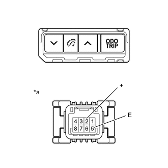
*a Component without harness connected
(Trip Switch)
Measure the resistance according to the value(s) in the table below.
Standard Resistance Tester Connection Condition Specified Condition 2 (+) - 5 (E) Trip switch pressed Below 1 Ω Trip switch not pressed 10 kΩ or higher If the result is not as specified, replace the trip switch.
-
-
Inspect light control rheostat switch
-
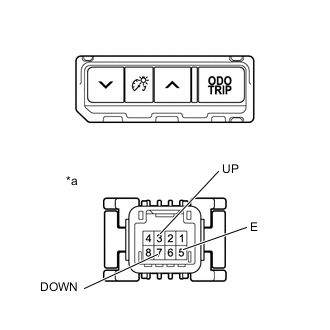
*a Component without harness connected
(Trip Switch)
Measure the resistance according to the value(s) in the table below.
Standard Resistance Tester Connection Condition Specified Condition 3 (UP) - 5 (E) Light control rheostat up switch pressed Below 1 Ω Light control rheostat up switch not pressed 10 kΩ or higher 7 (DOWN) - 5 (E) Light control rheostat down switch pressed Below 1 Ω Light control rheostat down switch not pressed 10 kΩ or higher If the result is not as specified, replace the trip switch.
-
-
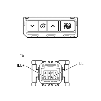
*a Component without harness connected
(Trip Switch)
Illumination inspection
-
Apply battery voltage to the trip switch and check that it illuminates.
OK Condition Specified Condition Battery positive (+) → Terminal 8 (ILL+)
Battery negative (-) → Terminal 6 (ILL-)
Illuminates If the result is not as specified, replace the trip switch.
-
-