DIGITAL REAR-VIEW MIRROR SYSTEM The Camera Indicator is not Displayed
DESCRIPTION
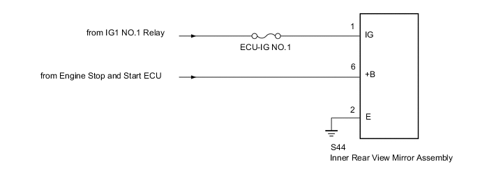
Power is supplied to the inner rear view mirror assembly through this circuit.
WIRING DIAGRAM
CAUTION / NOTICE / HINT
Note
Inspect the fuses for circuits related to this system before performing the following procedure.
PROCEDURE
-
CHECK HARNESS AND CONNECTOR (INNER REAR VIEW MIRROR ASSEMBLY - BATTERY)
-
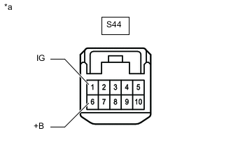
*a Front view of wire harness connector
(to Inner Rear View Mirror Assembly)
Disconnect the inner rear view mirror assembly connector.
-
Measure the voltage according to the value(s) in the table below.
Standard Voltage Tester Connection Condition Specified Condition S44-1 (IG) - Body ground Engine switch on (IG) 11 to 14 V S44-6 (+B) - Body ground Always 10.5 to 16 V Result Proceed to OK NG
NG 
REPAIR OR REPLACE HARNESS OR CONNECTOR
OK 
-
-
CHECK HARNESS AND CONNECTOR (INNER REAR VIEW MIRROR ASSEMBLY - BODY GROUND)
-
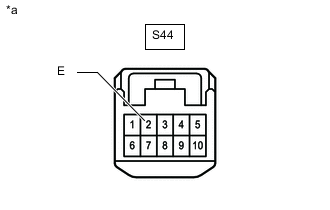
*a Front view of wire harness connector
(to Inner Rear View Mirror Assembly)
Disconnect the inner rear view mirror assembly connector.
-
Measure the resistance according to the value(s) in the table below.
Standard Resistance Tester Connection Condition Specified Condition S44-2 (E) - Body ground Always Below 1 Ω Result Proceed to OK NG
OK
REPLACE INNER REAR VIEW MIRROR ASSEMBLY Click here
NG
REPAIR OR REPLACE HARNESS OR CONNECTOR
-