METER / GAUGE SYSTEM Tachometer Malfunction
DESCRIPTION
In this circuit, the combination meter assembly receives engine speed signals from the ECM via the CAN communication system. The combination meter assembly displays the engine speed calculated based on the data received from the ECM.
WIRING DIAGRAM
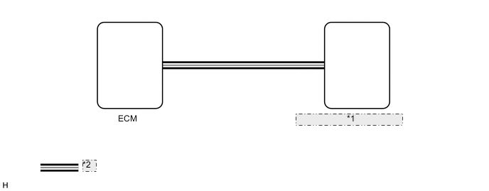
| *1 | Combination Meter Assembly |
| *2 | CAN Communication Line |
CAUTION / NOTICE / HINT
Note
When replacing the combination meter assembly, always replace it with a new one. If a combination meter assembly which was installed to another vehicle is used, the information stored in it will not match the information from the vehicle and a DTC may be stored.
PROCEDURE
-
CHECK CAN COMMUNICATION SYSTEM
-
Check if CAN communication DTCs are output.
for LHD: Click here
for RHD: Click here
Result Result Proceed to CAN communication DTCs are not output. A CAN communication DTCs are output.(for LHD) B CAN communication DTCs are output.(for RHD) C
B 
GO TO CAN COMMUNICATION SYSTEM Click here
C
GO TO CAN COMMUNICATION SYSTEM Click here
A 
-
-
CHECK FOR DTC
-
Check if SFI system DTCs are output.
-
for 2GR-FKS:
-
for 2AR-FE:
Powertrain > Engine > Trouble CodesResult Result Proceed to SFI system DTCs are not output. A SFI system DTCs are output. (for 2GR-FKS) B SFI system DTCs are output. (for 2AR-FE) C -
B
GO TO SFI SYSTEM Click here
C
GO TO SFI SYSTEM Click here
A
-
-
PERFORM ACTIVE TEST USING GTS (TACHOMETER OPERATION)
-
Connect the GTS to the DLC3.
-
Turn the engine switch on (IG).
-
Turn the GTS on.
-
Enter the following menus: Body Electrical / Combination Meter / Active Test.
-
Check the operation by referring to the table below.
Body Electrical > Combination Meter > Active TestTester Display Measurement Item Control Range Diagnostic Note TachoMeter Operation Tachometer OFF, 0, 1000, 2000, 3000, 4000, 5000, 6000, 7000 -
Body Electrical > Combination Meter > Active TestTester Display TachoMeter Operation OK Tachometer indication is normal. Result Result Proceed to OK (for 2GR-FKS) A OK (for 2AR-FE) B NG C
A
REPLACE ECM Click here
B
REPLACE ECM Click here
C
REPLACE COMBINATION METER ASSEMBLY Click here
-