METER / GAUGE SYSTEM Entire Combination Meter does not Operate
DESCRIPTION
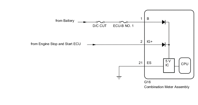
This circuit is the power source circuit for the combination meter assembly. This circuit provides two types of power sources; one is a constant power source, and the other is an IG power source.
WIRING DIAGRAM
CAUTION / NOTICE / HINT
Note
Inspect the fuses of circuits related to this system before performing the following procedure.
PROCEDURE
-
CHECK HARNESS AND CONNECTOR (ES AND B TERMINAL)
-
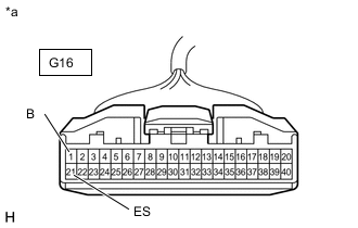
*a Front view of wire harness connector
(to Combination Meter Assembly)
Disconnect the combination meter assembly connector.
-
Measure the resistance according to the value(s) in the table below.
Standard Resistance Tester Connection Condition Specified Condition G16-21 (ES) - Body ground Always Below 1 Ω -
Measure the voltage according to the value(s) in the table below.
Standard Voltage Tester Connection Condition Specified Condition G16-1 (B) - Body ground Always 11 to 14 V Result Proceed to OK NG
NG 
REPAIR OR REPLACE HARNESS OR CONNECTOR
OK 
-
-
CHECK HARNESS AND CONNECTOR (IG+ TERMINAL)
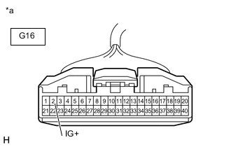
*a Front view of wire harness connector
(to Combination Meter Assembly)
-
Measure the voltage according to the value(s) in the table below.
Standard Voltage Tester Connection Switch Condition Specified Condition G16-2 (IG+) - Body ground Engine switch off Below 1 V Engine switch on (IG) 11 to 14 V Result Result Proceed to OK A NG (for 2AR-FE) B NG (for 2GR-FKS) C
A
REPLACE COMBINATION METER ASSEMBLY Click here
B
GO TO STOP AND START SYSTEM Click here
C
GO TO STOP AND START SYSTEM Click here
-