METER / GAUGE SYSTEM, Diagnostic DTC:B1507, B1508
| DTC Code | DTC Name |
|---|---|
| B1507 | Open in Turn Signal Circuit |
| B1508 | Short in Turn Signal / Hazard Flasher Circuit |
DESCRIPTION
These DTCs are stored when the combination meter assembly detects an open in a turn signal light circuit, a short in a turn signal light circuit, or a short in the hazard warning light circuit.
| DTC No. | Detection Item | DTC Detection Condition | Trouble Area |
|---|---|---|---|
| B1507 | Open in Turn Signal Circuit | Both conditions are met:
|
|
| B1508 | Short in Turn Signal / Hazard Flasher Circuit | Both conditions are met:
|
|
WIRING DIAGRAM
CAUTION / NOTICE / HINT
Note
-
When replacing the combination meter assembly, make sure to replace it with a new one.
-
Inspect the bulbs for circuits related to this system before performing the following inspection procedure.
PROCEDURE
-
CHECK FOR DTC
-
Clear the DTCs.
Body Electrical > Combination Meter > Clear DTCs -
Recheck for DTCs and check that no DTCs are output.
Body Electrical > Combination Meter > Trouble CodesOK B1507 and B1508 are not output. Result Proceed to OK NG
OK 
USE SIMULATION METHOD TO CHECK Click here
NG 
-
-
CHECK LIGHTS
-
Check the illumination of each turn signal light.
Result Result Proceed to Front turn signal light LH does not illuminate. A Front turn signal light RH does not illuminate. B Side turn signal light LH does not illuminate. C Side turn signal light RH does not illuminate. D Rear LH side turn signal light does not illuminate. E Rear RH side turn signal light does not illuminate. F
B 
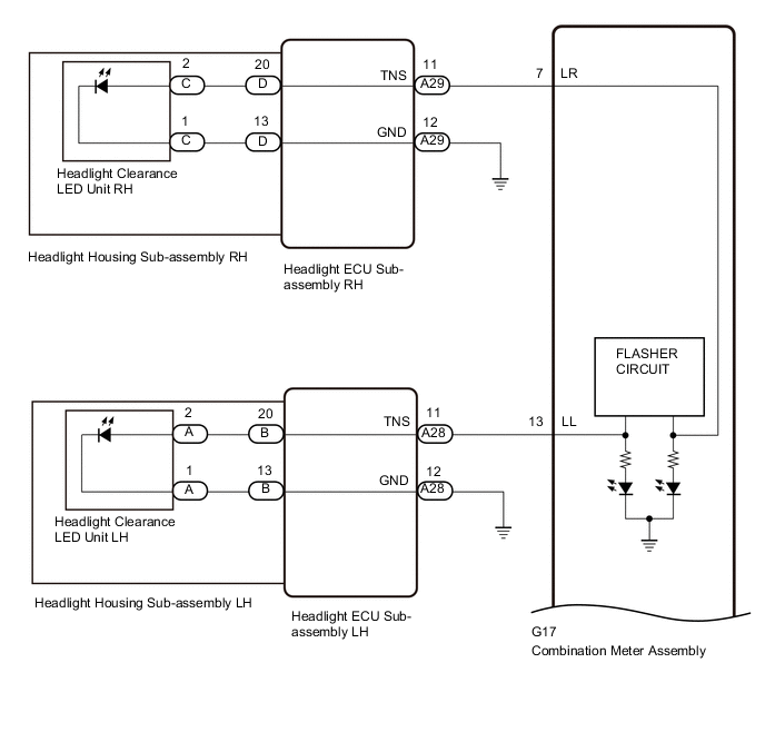
CHECK HARNESS AND CONNECTOR (HEADLIGHT ECU SUB-ASSEMBLY RH - COMBINATION METER ASSEMBLY) Click here
C
INSPECT OUTER REAR VIEW MIRROR ASSEMBLY LH Click here
D
INSPECT OUTER REAR VIEW MIRROR ASSEMBLY RH Click here
E
INSPECT LIGHTS Click here
F
INSPECT LIGHTS Click here
A
-
-
CHECK HARNESS AND CONNECTOR (HEADLIGHT ECU SUB-ASSEMBLY LH - COMBINATION METER ASSEMBLY)
-
Disconnect the A28 headlight ECU sub-assembly LH connector.
-
Disconnect the G17 combination meter assembly connector.
-
Measure the resistance according to the value (s) in the table below.
Standard Resistance Tester Connection Condition Specified Condition A28-11 (TNS) - G17-13 (LL) Always Below 1 Ω A28-12 (GND) - Body ground Always Below 1 Ω A28-11 (TNS) or G17-13 (LL) - Body ground Always 10 kΩ or higher Result Proceed to OK NG
NG
REPAIR OR REPLACE HARNESS OR CONNECTOR
OK
-
-
CHECK HEADLIGHT ECU SUB-ASSEMBLY LH (POWER SOURCE)
-
*a Front view of wire harness connector
(to Headlight ECU Sub-assembly LH)
Disconnect the A28 headlight ECU sub-assembly LH connector.
-
Measure the resistance according to the value (s) in the table below.
Standard Resistance Tester Connection Switch Condition Specified Condition A28-11 (TNS) - Body ground Engine switch on (IG), LH turn signal switch off Below 1 Ω Engine switch on (IG), LH turn signal switch on Below 1 Ω Result Proceed to OK NG
NG
REPLACE COMBINATION METER ASSEMBLY Click here
OK
-
-
CHECK HEADLIGHT ECU SUB-ASSEMBLY LH
-
Remove the headlight ECU sub-assembly LH.
-
*1 Headlight ECU sub-assembly LH Reconnect the A28 headlight ECU sub-assembly LH connector.
-
Measure the resistance according to the value (s) in the table below.
Standard Resistance Tester Connection Switch Condition Specified Condition B-20 - B-13 Engine switch on (IG), LH turn signal switch off Below 1 V Engine switch on (IG), LH turn signal switch on Below 1 V ←→ 11 to 14 V Result Proceed to OK NG
NG
REPLACE HEADLIGHT ECU SUB-ASSEMBLY LH Click here
OK
-
-
CHECK WIRE HARNESS AND CONNECTOR (HEADLIGHT ECU SUB-ASSEMBLY LH - HEADLIGHT CLEARANCE LED UNIT LH)
-
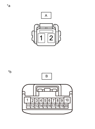
*a Front view of wire harness connector
(to headlight Clearance LED Unit LH)
*b Front view of wire harness connector
(to Headlight ECU Sub-assembly LH)
Remove the headlight ECU sub-assembly LH.
-
Remove the headlight clearance LED unit LH.
-
for ALPHARD:
-
for VELLFIRE:
-
-
Measure the resistance according to the value (s) in the table below.
Standard Resistance Tester Connection Condition Specified Condition A-2 - B-20 Always Below 1 Ω A-2 or B-20 - Body ground Always 10 kΩ or higher A-1 - B-13 Always Below 1 Ω A-1 or B-13 - Body ground Always 10 kΩ or higher Result Result Proceed to OK (for ALPHARD) A OK (for VELLFIRE) B NG (for ALPHARD) C NG (for VELLFIRE) D
A
REPLACE HEADLIGHT CLEARANCE LED UNIT LH Click here
B
REPLACE HEADLIGHT CLEARANCE LED UNIT LH Click here
C
REPLACE HEADLIGHT HOUSING SUB-ASSEMBLY LH Click here
D
REPLACE HEADLIGHT HOUSING SUB-ASSEMBLY LH Click here
-
-
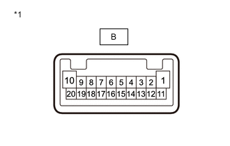
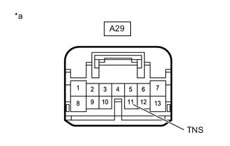
CHECK HARNESS AND CONNECTOR (HEADLIGHT ECU SUB-ASSEMBLY RH - COMBINATION METER ASSEMBLY)
-
Disconnect the A29 headlight ECU sub-assembly RH connector.
-
Disconnect the G17 combination meter assembly connector.
-
Measure the resistance according to the value (s) in the table below.
Standard Resistance Tester Connection Condition Specified Condition A29-11 (TNS) - G17-7 (LR) Always Below 1 Ω A28-12 (GND) - Body ground Always Below 1 Ω A28-11 (TNS) or G17-7 (LR) - Body ground Always 10 kΩ or higher Result Proceed to OK NG
NG
REPAIR OR REPLACE HARNESS OR CONNECTOR
OK
-
-
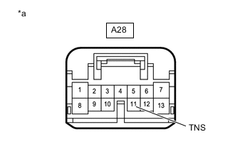
CHECK HEADLIGHT ECU SUB-ASSEMBLY RH (POWER SOURCE)
-
*a Front view of wire harness connector
(to Headlight ECU Sub-assembly RH)
Disconnect the A29 headlight ECU sub-assembly RH connector.
-
Measure the resistance according to the value (s) in the table below.
Standard Resistance Tester Connection Switch Condition Specified Condition A29-11 (TNS) - Body ground Engine switch on (IG), RH turn signal switch off Below 1 Ω Engine switch on (IG), RH turn signal switch on Below 1 Ω Result Proceed to OK NG
NG
REPLACE COMBINATION METER ASSEMBLY Click here
OK
-
-
CHECK HEADLIGHT ECU SUB-ASSEMBLY RH
-
Remove the headlight ECU sub-assembly RH.
-

*1 Headlight ECU sub-assembly RH Reconnect the A29 headlight ECU sub-assembly RH connector.
-
Measure the resistance according to the value (s) in the table below.
Standard Resistance Tester Connection Switch Condition Specified Condition D-20 - D-13 Engine switch on (IG), RH turn signal switch off Below 1 V Engine switch on (IG), RH turn signal switch on Below 1 V ←→ 11 to 14 V Result Proceed to OK NG
NG
REPLACE HEADLIGHT ECU SUB-ASSEMBLY RH Click here
OK
-
-
CHECK WIRE HARNESS AND CONNECTOR (HEADLIGHT ECU SUB-ASSEMBLY RH - HEADLIGHT CLEARANCE LED UNIT RH)
-

*a Front view of wire harness connector
(to headlight Clearance LED Unit RH)
*b Front view of wire harness connector
(to Headlight ECU Sub-assembly RH)
Remove the headlight ECU sub-assembly RH.
-
Remove the headlight clearance LED unit RH.
-
for ALPHARD:
-
for VELLFIRE:
-
-
Measure the resistance according to the value (s) in the table below.
Standard Resistance Tester Connection Condition Specified Condition C-2 - D-20 Always Below 1 Ω C-2 or D-20 - Body ground Always 10 kΩ or higher C-1 - D-13 Always Below 1 Ω C-1 or D-13 - Body ground Always 10 kΩ or higher Result Result Proceed to OK (for ALPHARD) A OK (for VELLFIRE) B NG (for ALPHARD) C NG (for VELLFIRE) D
A
REPLACE HEADLIGHT CLEARANCE LED UNIT RH Click here
B
REPLACE HEADLIGHT CLEARANCE LED UNIT RH Click here
C
REPLACE HEADLIGHT HOUSING SUB-ASSEMBLY RH Click here
D
REPLACE HEADLIGHT HOUSING SUB-ASSEMBLY RH Click here
-
-
INSPECT OUTER REAR VIEW MIRROR ASSEMBLY LH
-
Remove the outer rear view mirror assembly LH.
-
Inspect the outer rear view mirror assembly LH.
Result Proceed to OK NG
OK
REPAIR OR REPLACE HARNESS OR CONNECTOR (OUTER REAR VIEW MIRROR ASSEMBLY LH - COMBINATION METER ASSEMBLY)
NG
-
-
INSPECT SIDE TURN SIGNAL LIGHT ASSEMBLY LH
-
Remove the side turn signal light assembly LH.
-
Inspect the side turn signal light assembly LH.
Result Proceed to OK NG
OK
REPLACE OUTER REAR VIEW MIRROR ASSEMBLY LH Click here
NG
REPLACE SIDE TURN SIGNAL LIGHT ASSEMBLY LH Click here
-
-
INSPECT OUTER REAR VIEW MIRROR ASSEMBLY RH
-
Remove the outer rear view mirror assembly RH.
-
Inspect the outer rear view mirror assembly RH.
Result Proceed to OK NG
OK
REPAIR OR REPLACE HARNESS OR CONNECTOR
NG
-
-
INSPECT SIDE TURN SIGNAL LIGHT ASSEMBLY RH
-
Remove the side turn signal light assembly RH.
-
Inspect the side turn signal light assembly RH.
Result Proceed to OK NG
OK
REPLACE OUTER REAR VIEW MIRROR ASSEMBLY RH Click here
NG
REPLACE SIDE TURN SIGNAL LIGHT ASSEMBLY RH Click here
-
-
INSPECT LIGHTS
-
Inspect the illumination of each turn signal light.
Result Result Proceed to All LH side rear turn signal lights do not blink. A Rear light assembly LH does not illuminate. B Rear combination light assembly LH does not illuminate. C
B
INSPECT REAR LIGHT ASSEMBLY LH Click here
C
INSPECT REAR COMBINATION LIGHT ASSEMBLY LH Click here
A
-
-
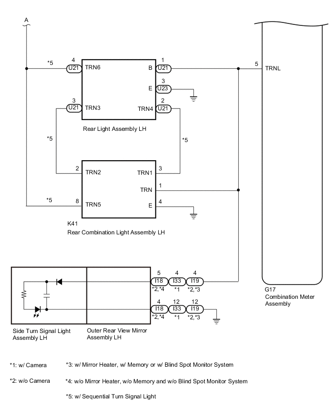
CHECK HARNESS AND CONNECTOR (REAR LIGHT ASSEMBLY LH AND REAR COMBINATION LIGHT ASSEMBLY LH - COMBINATION METER ASSEMBLY AND BODY GROUND)
-
Disconnect the U21 and U23 rear light assembly LH connectors.
-
Disconnect the K41 rear combination light assembly LH connector.
-
Disconnect the G17 combination meter assembly connector.
-
Measure the resistance according to the value(s) in the table below.
Standard Resistance Rear light assembly LH Tester Connection Condition Specified Condition U21-1 (B) - G17-5 (TRNL) Always Below 1 Ω U23-3 (E) - Body ground Always Below 1 Ω U21-1 (B) or G17-5 (TRNL) - Body ground Always 10 kΩ or higher Rear combination light assembly LH Tester Connection Condition Specified Condition K41-1 (TRN) - G17-5 (TRNL) Always Below 1 Ω K41-4 (E) - Body ground Always Below 1 Ω K41-1 (TRN) or G17-5 (TRNL) - Body ground Always 10 kΩ or higher Result Proceed to OK NG
NG
REPAIR OR REPLACE HARNESS OR CONNECTOR
OK
-
-
CHECK HARNESS AND CONNECTOR (REAR LIGHT ASSEMBLY LH AND REAR COMBINATION LIGHT ASSEMBLY LH - COMBINATION METER ASSEMBLY AND BODY GROUND)
-
Disconnect the U21 rear light assembly LH connector.
-
Disconnect the K41 rear combination light assembly LH connector.
-
Disconnect the G16 combination meter assembly connector.
-
Measure the resistance according to the value(s) in the table below.
Standard Resistance Tester Connection Condition Specified Condition K41-2 (TRN2) - U21-3 (TRN3) Always Below 1 Ω K41-2 (TRN2) or U21-3 (TRN3) - Body ground Always 10 kΩ or higher K41-3 (TRN1) - U21-2 (TRN4) Always Below 1 Ω K41-3 (TRN1) or U21-2 (TRN4) - Body ground Always 10 kΩ or higher U21-4 (TRN6) - G16-17 (SYC1) Always Below 1 Ω U21-4 (TRN6) or G16-17 (SYC1) - Body ground Always 10 kΩ or higher K41-8 (TRN5) - G16-17 (SYC1) Always Below 1 Ω K41-8 (TRN5) or G16-17 (SYC1) - Body ground Always 10 kΩ or higher Result Proceed to OK NG
NG
REPAIR OR REPLACE HARNESS OR CONNECTOR
OK
-
-
INSPECT REAR LIGHT ASSEMBLY LH
-
Remove the rear light assembly LH.
-
for ALPHARD:
-
for VELLFIRE:
-
-
Inspect the rear light assembly LH.
-
for ALPHARD:
-
for VELLFIRE:
Result Result Proceed to OK A NG (for ALPHARD) B NG (for VELLFIRE) C -
B
REPLACE REAR LIGHT ASSEMBLY LH Click here
C
REPLACE REAR LIGHT ASSEMBLY LH Click here
A
-
-
INSPECT REAR COMBINATION LIGHT ASSEMBLY LH
-
Remove the rear combination light assembly LH.
-
for ALPHARD:
-
for VELLFIRE:
-
-
Inspect the rear combination light assembly LH.
-
for ALPHARD:
-
for VELLFIRE:
Result Result Proceed to OK A NG (for ALPHARD) B NG (for VELLFIRE) C -
A
REPLACE COMBINATION METER ASSEMBLY Click here
B
REPLACE REAR COMBINATION LIGHT ASSEMBLY LH Click here
C
REPLACE REAR COMBINATION LIGHT ASSEMBLY LH Click here
-
-
INSPECT REAR LIGHT ASSEMBLY LH
-
Remove the rear light assembly LH.
-
for ALPHARD:
-
for VELLFIRE:
-
-
Inspect the rear light assembly LH.
-
for ALPHARD:
-
for VELLFIRE:
Result Result Proceed to OK A NG (for ALPHARD) B NG (for VELLFIRE) C -
A
REPAIR OR REPLACE HARNESS OR CONNECTOR (REAR LIGHT ASSEMBLY LH - COMBINATION METER ASSEMBLY)
B
REPLACE REAR LIGHT ASSEMBLY LH Click here
C
REPLACE REAR LIGHT ASSEMBLY LH Click here
-
-
INSPECT REAR COMBINATION LIGHT ASSEMBLY LH
-
Remove the rear combination light assembly LH.
-
for ALPHARD:
-
for VELLFIRE:
-
-
Inspect the rear combination light assembly LH.
-
for ALPHARD:
-
for VELLFIRE:
Result Result Proceed to OK A NG (for ALPHARD) B NG (for VELLFIRE) C -
A
REPAIR OR REPLACE HARNESS OR CONNECTOR (REAR COMBINATION LIGHT ASSEMBLY LH - COMBINATION METER ASSEMBLY)
B
REPLACE REAR COMBINATION LIGHT ASSEMBLY LH Click here
C
REPLACE REAR COMBINATION LIGHT ASSEMBLY LH Click here
-
-
INSPECT LIGHTS
-
Inspect the illumination of each turn signal light.
Result Result Proceed to All RH side rear turn signal lights do not blink. A Rear light assembly RH does not illuminate. B Rear combination light assembly RH does not illuminate. C
B
INSPECT REAR LIGHT ASSEMBLY RH Click here
C
INSPECT REAR COMBINATION LIGHT ASSEMBLY RH Click here
A
-
-
CHECK HARNESS AND CONNECTOR (REAR LIGHT ASSEMBLY RH AND REAR COMBINATION LIGHT ASSEMBLY RH - COMBINATION METER ASSEMBLY AND BODY GROUND)
-
Disconnect the U20 and U22 rear light assembly RH connectors.
-
Disconnect the L39 rear combination light assembly RH connector.
-
Disconnect the G17 combination meter assembly connector.
-
Measure the resistance according to the value(s) in the table below.
Standard Resistance Rear light assembly RH Tester Connection Condition Specified Condition U22-1 (B) - G17-11 (TRNR) Always Below 1 Ω U20-3 (E) - Body ground Always Below 1 Ω U22-1 (B) or G17-11 (TRNR) - Body ground Always 10 kΩ or higher Rear combination light assembly RH Tester Connection Condition Specified Condition L39-1 (TRN) - G17-11 (TRNR) Always Below 1 Ω L39-4 (E) - Body ground Always Below 1 Ω L39-1 (TRN) or G17-11 (TRNR) - Body ground Always 10 kΩ or higher Result Proceed to OK NG
NG
REPAIR OR REPLACE HARNESS OR CONNECTOR
OK
-
-
CHECK HARNESS AND CONNECTOR (REAR LIGHT ASSEMBLY RH AND REAR COMBINATION LIGHT ASSEMBLY RH - COMBINATION METER ASSEMBLY AND BODY GROUND)
-
Disconnect the U22 rear light assembly RH connector.
-
Disconnect the L39 rear combination light assembly RH connector.
-
Disconnect the G16 combination meter assembly connector.
-
Measure the resistance according to the value(s) in the table below.
Standard Resistance Tester Connection Condition Specified Condition L39-2 (TRN2) - U22-3 (TRN3) Always Below 1 Ω L39-2 (TRN2) or U22-3 (TRN3) - Body ground Always 10 kΩ or higher L39-3 (TRN1) - U22-2 (TRN4) Always Below 1 Ω L39-3 (TRN1) or U22-2 (TRN4) - Body ground Always 10 kΩ or higher U22-4 (TRN6) - G16-17 (SYC1) Always Below 1 Ω U22-4 (TRN6) or G16-17 (SYC1) - Body ground Always 10 kΩ or higher L39-8 (TRN5) - G16-17 (SYC1) Always Below 1 Ω L39-8 (TRN5) or G16-17 (SYC1) - Body ground Always 10 kΩ or higher Result Proceed to OK NG
NG
REPAIR OR REPLACE HARNESS OR CONNECTOR
OK
-
-
INSPECT REAR LIGHT ASSEMBLY RH
-
Remove the rear light assembly RH.
-
for ALPHARD:
-
for VELLFIRE:
-
-
Inspect the rear light assembly RH.
-
for ALPHARD:
-
for VELLFIRE:
Result Result Proceed to OK A NG (for ALPHARD) B NG (for VELLFIRE) C -
B
REPLACE REAR LIGHT ASSEMBLY RH Click here
C
REPLACE REAR LIGHT ASSEMBLY RH Click here
A
-
-
INSPECT REAR COMBINATION LIGHT ASSEMBLY RH
-
Remove the rear combination light assembly RH.
-
for ALPHARD:
-
for VELLFIRE:
-
-
Inspect the rear combination light assembly RH.
-
for ALPHARD:
-
for VELLFIRE:
Result Result Proceed to OK A NG (for ALPHARD) B NG (for VELLFIRE) C -
A
REPLACE COMBINATION METER ASSEMBLY Click here
B
REPLACE REAR COMBINATION LAMP ASSEMBLY RH Click here
C
REPLACE REAR COMBINATION LAMP ASSEMBLY RH Click here
-
-
INSPECT REAR LIGHT ASSEMBLY RH
-
Remove the rear light assembly RH.
-
for ALPHARD:
-
for VELLFIRE:
-
-
Inspect the rear light assembly RH.
-
for ALPHARD:
-
for VELLFIRE:
Result Result Proceed to OK A NG (for ALPHARD) B NG (for VELLFIRE) C -
A
REPAIR OR REPLACE HARNESS OR CONNECTOR (REAR LIGHT ASSEMBLY RH - COMBINATION METER ASSEMBLY)
B
REPLACE REAR LIGHT ASSEMBLY RH Click here
C
REPLACE REAR LIGHT ASSEMBLY RH Click here
-
-
INSPECT REAR COMBINATION LIGHT ASSEMBLY RH
-
Remove the rear combination light assembly RH.
-
for ALPHARD:
-
for VELLFIRE:
-
-
Inspect the rear combination light assembly RH.
-
for ALPHARD:
-
for VELLFIRE:
Result Result Proceed to OK A NG (for ALPHARD) B NG (for VELLFIRE) C -
A
REPAIR OR REPLACE HARNESS OR CONNECTOR (REAR COMBINATION LIGHT ASSEMBLY RH - COMBINATION METER ASSEMBLY)
B
REPLACE REAR COMBINATION LAMP ASSEMBLY RH Click here
C
REPLACE REAR COMBINATION LAMP ASSEMBLY RH Click here
-