METER / GAUGE SYSTEM, Diagnostic DTC:B1500
| DTC Code | DTC Name |
|---|---|
| B1500 | Fuel Sender Open Detected |
DESCRIPTION
This DTC is stored when the combination meter assembly detects a fuel sender gauge assembly malfunction via a direct line.
| DTC No. | Detection Item | DTC Detection Condition | Trouble Area |
|---|---|---|---|
| B1500 | Fuel Sender Open Detected | When IG voltage is 9.5 V or more and the following condition is detected:
|
|
WIRING DIAGRAM
-
for 2GR-FKS
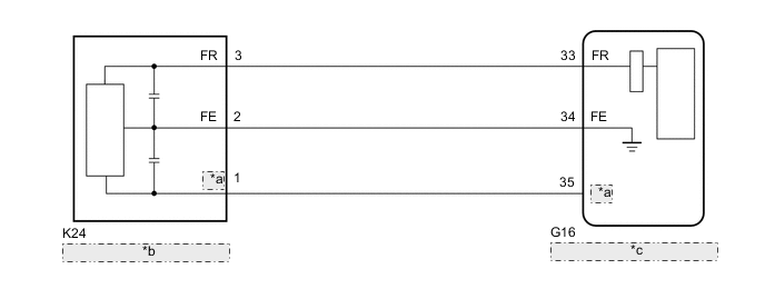
*a FV *b Fuel Sender Gauge Assembly *c Combination Meter Assembly -
for 2AR-FE
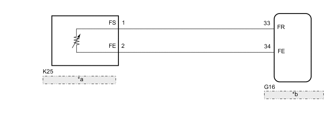
*a Fuel Sender Gauge Assembly *b Combination Meter Assembly
CAUTION / NOTICE / HINT
Note
When replacing the combination meter assembly, always replace it with a new one. If a combination meter assembly which was installed to another vehicle is used, the information stored in it will not match the information from the vehicle and a DTC may be stored.
PROCEDURE
-
READ VALUE USING GTS (FUEL INPUT)
-
Connect the GTS to the DLC3.
-
Turn the engine switch on (IG).
-
Turn the GTS on.
-
Enter the following menus: Body Electrical / Combination Meter / Data List.
-
Check the values by referring to the table below.
Body Electrical > Combination Meter > Data ListTester Display Measurement Item Range Normal Condition Diagnostic Note Fuel Input Fuel input Min.: 0 L, Max. 127.5 L Fuel sender input value Unit: Liter
Body Electrical > Combination Meter > Data ListTester Display Fuel Input Result Result Proceed to Fuel level data can be displayed on the GTS and DTC B1500 is output. A Fuel level data cannot be displayed on the GTS. (for 2GR-FKS) B Fuel level data cannot be displayed on the GTS. (for 2AR-FE) C
A 
REPLACE COMBINATION METER ASSEMBLY Click here
C 
INSPECT FUEL SENDER GAUGE ASSEMBLY Click here
B 
-
-
INSPECT FUEL SENDER GAUGE ASSEMBLY
-
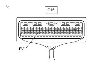
*a Component with harness connected
(Combination Meter Assembly)
Measure the resistance according to the value(s) in the table below.
Standard Resistance Tester Connection Switch Condition Specified Condition G16-35 (FV) - Body ground Engine switch on (IG) 4.5 to 5.5 V Result Proceed to OK NG
NG
REPLACE COMBINATION METER ASSEMBLY Click here
OK
-
-
INSPECT FUEL SENDER GAUGE ASSEMBLY
-
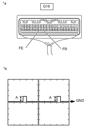
*a Component with harness connected
(Combination Meter Assembly)
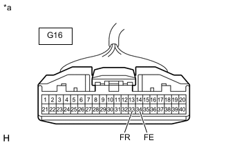
*b Waveform 1 Using an oscilloscope, check the waveform.
OK Tester Connection Condition Tool setting Specified Condition G16-33 (FR) - G16-34 (FE) Engine switch on (IG), fuel receiver gauge F → E 5 V/DIV., 20 ms./DIV. Pulse generation
(See waveform 1)
Tech Tips
The height of A is changed on the fuel amount.
(Fuel receiver gauge F → E [4.2 to 4.6 V → 0.4 to 0.7 V])
Result Proceed to OK NG
OK
REPLACE COMBINATION METER ASSEMBLY Click here
NG
-
-
CHECK HARNESS AND CONNECTOR (COMBINATION METER ASSEMBLY - FUEL SENDER GAUGE ASSEMBLY)
-
Disconnect the K25 fuel sender gauge assembly connector.
-
Measure the resistance according to the value(s) in the table below.
Standard Resistance Tester Connection Condition Specified Condition G16-33 (FR) - K24-3 (FR) Always Below 1 Ω G16-34 (FE) - K24-2 (FE) Always Below 1 Ω G16-35 (FV) - K24-1 (FV) Always Below 1 Ω G16-33 (FR) or K24-3 (FR) - Body ground Always 10 kΩ or higher G16-34 (FE) or K24-2 (FE) - Body ground Always 10 kΩ or higher G16-35 (FV) or K24-1 (FV) - Body ground Always 10 kΩ or higher Result Proceed to OK NG
NG
REPAIR OR REPLACE HARNESS OR CONNECTOR
OK
-
-
INSPECT FUEL SENDER GAUGE ASSEMBLY
-
Remove the fuel sender gauge assembly.
-
Inspect the fuel sender gauge assembly.
Result Proceed to OK NG
OK
REPLACE COMBINATION METER ASSEMBLY Click here
NG
REPLACE FUEL SENDER GAUGE ASSEMBLY Click here
-
-
INSPECT FUEL SENDER GAUGE ASSEMBLY
-
*a Front view of wire harness connector
(to Combination Meter Assembly)
Disconnect the combination meter assembly connector.
-
Measure the resistance according to the value(s) in the table below.
Standard Resistance Tester Connection Condition Specified Condition G16-33 (FR) - G16-34 (FE) Always 13.0 to 415.5 Ω Result Proceed to OK NG
OK
REPLACE COMBINATION METER ASSEMBLY Click here
NG
-
-
CHECK HARNESS AND CONNECTOR (COMBINATION METER ASSEMBLY - FUEL SENDER GAUGE ASSEMBLY)
-
Disconnect the K25 fuel sender gauge assembly connector.
-
Measure the resistance according to the value(s) in the table below.
Standard Resistance Tester Connection Condition Specified Condition G16-33 (FR) - K25-1 (FS) Always Below 1 Ω G16-34 (FE) - K25-2 (FE) Always Below 1 Ω G16-33 (FR) or K25-1 (FS) - Body ground Always 10 kΩ or higher G16-34 (FE) or K25-2 (FE) - Body ground Always 10 kΩ or higher Result Proceed to OK NG
NG
REPAIR OR REPLACE HARNESS OR CONNECTOR
OK
-
-
INSPECT FUEL SENDER GAUGE ASSEMBLY
-
Remove the fuel sender gauge assembly.
-
Inspect the fuel sender gauge assembly.
Result Proceed to OK NG
OK
REPLACE COMBINATION METER ASSEMBLY Click here
NG
REPLACE FUEL SENDER GAUGE ASSEMBLY Click here
-