REAR AIR CONDITIONING UNIT INSTALLATION
PROCEDURE
-
INSTALL REAR COOLING UNIT ASSEMBLY
-
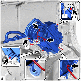
*1 Guide Attach the guide to install the rear cooling unit assembly.
-
Install the rear cooling unit assembly with the 3 bolts and tighten the bolts in the order shown in the illustration.
- Torque:
- 9.8 N*m { 100 kgf*cm, 87 in.*lbf }
-
Connect the drain cooler hose to the grommet.
-
Connect each connector.
-
Attach the harness clamp.
-
Attach the claw to connect the penetration cover to the body.
-
Install the 2 bolts.
- Torque:
- 5.4 N*m { 55 kgf*cm, 48 in.*lbf }
-
-
INSTALL NO. 1 COOLER AIR DUCT
-

Order of Installation Install the No. 1 cooler air duct as shown in the illustration.
-
-
INSTALL COOLER PLATE
-
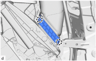
Attach the claw to install the cooler plate.
-
-
INSTALL REAR NO. 2 SEAT TRACK ASSEMBLY RH
-
INSTALL INNER UPPER ROOF SIDE GARNISH RH
-
INSTALL REAR QUARTER TRIM PANEL ASSEMBLY RH
-
INSTALL ROPE HOOK ASSEMBLY
-
INSTALL NO. 1 LUGGAGE COMPARTMENT TRIM HOOK
-
INSTALL DECK SIDE GARNISH RH
-
INSTALL REAR DOOR SCUFF PLATE RH
-
INSTALL BACK DOOR SCUFF PLATE
-
INSTALL REAR UPPER NO. 1 FLOOR BOARD PLATE
-
INSTALL UTILITY BOX SUB-ASSEMBLY
-
INSTALL REAR NO. 3 FLOOR BOARD ASSEMBLY
-
INSTALL REAR NO. 2 FLOOR BOARD ASSEMBLY
-
INSTALL REAR NO. 1 FLOOR BOARD ASSEMBLY
-
INSTALL REAR NO. 2 SEAT ASSEMBLY RH
-
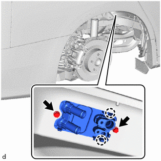
INSTALL COOLER REFRIGERANT LIQUID PIPE D
-
Remove the vinyl tape from the cooler refrigerant liquid pipe D.
-
Sufficiently apply compressor oil to a new O-ring and the fitting surface of the cooler refrigerant liquid pipe D.
Compressor Oil ND-OIL 8 or equivalent -
Install the O-ring to the cooler refrigerant liquid pipe D.
Note
Keep the O-rings and O-ring fitting surfaces free of foreign matter.
-
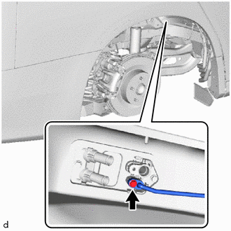
Connect the cooler refrigerant liquid pipe D with the bolt.
- Torque:
- 5.4 N*m { 55 kgf*cm, 48 in.*lbf }
-
-
INSTALL COOLER REFRIGERANT SUCTION PIPE B
-
Remove the vinyl tape from the cooler refrigerant suction pipe B.
-
Sufficiently apply compressor oil to a new O-ring and the fitting surface of the cooler refrigerant suction pipe B.
Compressor Oil ND-OIL 8 or equivalent -
Install the O-ring to the cooler refrigerant suction pipe B.
Note
Keep the O-rings and O-ring fitting surfaces free of foreign matter.
-
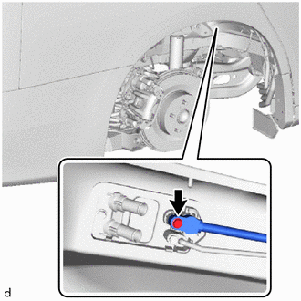
Connect the cooler refrigerant suction pipe B with the bolt.
- Torque:
- 5.4 N*m { 55 kgf*cm, 48 in.*lbf }
-
-
INSTALL HEATER WATER HOSE OUTLET B
-
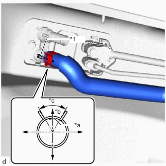
*1 Rib *a Marking (White) *b Back Side *c Clip Installation Angle (90°) Align the rib of the rear cooling unit assembly with the marking (white). Connect the heater water hose outlet B and install the clip within the range shown in the illustration.
-
-
INSTALL HEATER WATER HOSE INLET B
-
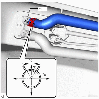
*1 Rib *a Marking (Yellow) *b Back Side *c Clip Installation Angle (90°) Align the rib of the rear cooling unit assembly with the marking (yellow). Connect the heater water hose inlet B and install the clip within the range shown in the illustration.
-
-
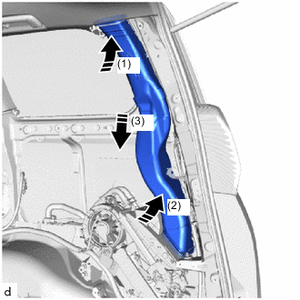
INSTALL REAR WHEEL HOUSE LINER RH
-
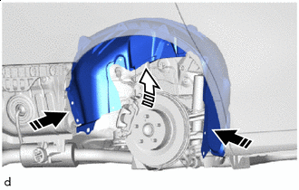
Install in this Direction (1) 
Install in this Direction (2) Bend the rear wheel house liner RH inward and attach it to the stud bolts to install the rear wheel house liner RH.
-
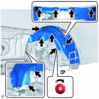
Rotation Direction Rotate and install the 11 screw clips with your fingers.
-
Install the 3 screws.
-
-
INSTALL WHEEL ASSEMBLY (Rear RH)
-
INSTALL REAR BUMPER COVER
-
ADD ENGINE COOLANT
-
for 2AR-FE:
-
for 2GR-FE:
-
-
INSPECT FOR COOLANT LEAK
-
for 2AR-FE:
-
for 2GR-FE:
-
-
CHARGE AIR CONDITIONING SYSTEM WITH REFRIGERANT
-
WARM UP ENGINE
-
INSPECT FOR REFRIGERANT LEAK
-
INITIALIZATION SERVO MOTOR