CEILING LIGHT INSTALLATION
CAUTION / NOTICE / HINT
Tech Tips
-
Use the same procedure for RHD and LHD vehicles.
-
The procedure listed below is for LHD vehicles.
-
Use the same procedure for the RH and LH sides.
-
The procedure listed below is for the LH side.
PROCEDURE
-
INSTALL NO. 1 INTERIOR ILLUMINATION LIGHT ASSEMBLY LH
-
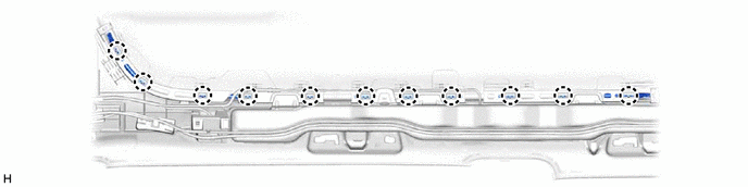
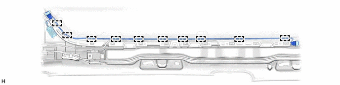
for Normal Roof:
-
Attach the claw to install the No. 1 interior illumination light assembly LH.
-
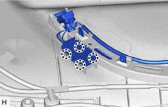
Install 2 new cable ties as shown in the illustration.
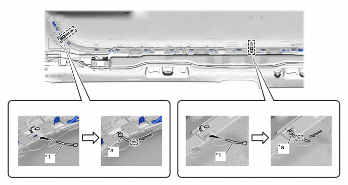
*1 Cable Tie (62371-58010) - - *a White Line - - 
Install in this Direction (1) 
Install in this Direction (2) 
Attach the guide - - Note
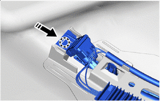
Attach the cable tie as shown in the illustration.
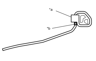
*a Lock Part *b White Line
-
-
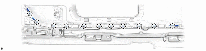
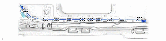
for Sliding Roof:
-
Attach the claw to install the No. 1 interior illumination light assembly LH.
-
Install 2 new cable ties as shown in the illustration.
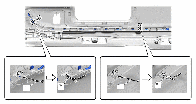
*1 Cable Tie (62371-58010) - - *a White Line - - Install in this Direction (1) Install in this Direction (2) Attach the guide - - Note
Attach the cable tie as shown in the illustration.
*a Lock Part *b White Line
-
-
-
INSTALL INTERIOR ILLUMINATION LIGHT SUB-ASSEMBLY
-
for Normal Roof:
-
Attach the clamp to install the interior illumination light sub-assembly.
-
-
for Sliding Roof:
-
Attach the clamp to install the interior illumination light sub-assembly.
-
-
Slide Slide the rear portion of the interior illumination light as shown in the illustration and attach the claw to install it to the roof headlining assembly.
-
Slide Slide the front portion of the interior illumination light as shown in the illustration and attach the claw to install it to the roof headlining assembly.
-
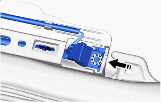
Attach the claw to install the power sub-assembly to the roof headlining assembly.
-
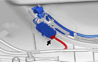
Connect the connector.
-
-
INSTALL ROOF HEADLINING ASSEMBLY