LIGHTING SYSTEM Engine Switch Illumination Circuit
DESCRIPTION
The illuminated entry system controls the engine switch illumination.
WIRING DIAGRAM
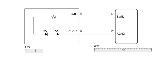
| *1 | Engine Switch |
| *2 | Certification ECU (Smart Key ECU Assembly) |
CAUTION / NOTICE / HINT
Note
Before replacing the certification ECU (smart key ECU assembly), refer to the smart entry and start system (for Entry Function) precaution.
PROCEDURE
-
PERFORM ACTIVE TEST USING GTS (POWER/ENGINE SW LIGHT)
-
Using the GTS, perform the Active Test.
Body Electrical > Entry&Start > Active TestTester Display Measurement Item Control Range Diagnostic Note Power/Engine SW Light Engine switch illumination ON or OFF Approximately 20 seconds after turning the engine switch off with all the doors closed, check the operation once the engine switch lettering illumination turns off.
Body Electrical > Entry&Start > Active TestTester Display Power/Engine SW Light OK Engine switch illumination illuminates. Result Proceed to OK NG
OK 
PROCEED TO NEXT SUSPECTED AREA SHOWN IN PROBLEM SYMPTOMS TABLE Click here
NG 
-
-
INSPECT ENGINE SWITCH
-
Remove the engine switch.
for 2AR-FE:
for 2GR-FE:
-
Inspect the engine switch.
for 2AR-FE:
for 2GR-FE:
Result Proceed to OK NG
NG
REPLACE ENGINE SWITCH for 2AR-FE: REPLACE ENGINE SWITCH Click here
REPLACE ENGINE SWITCH for 2GR-FE: REPLACE ENGINE SWITCH Click hereOK
-
-
CHECK HARNESS AND CONNECTOR (ENGINE SWITCH - CERTIFICATION ECU [SMART KEY ECU ASSEMBLY])
-
Disconnect the G24 engine switch connector.
-
Disconnect the G22 certification ECU (smart key ECU assembly) connector.
-
Measure the resistance according to the value(s) in the table below.
Standard Resistance Tester Connection Condition Specified Condition G24-9 (SWIL) - G22-17 (SWIL) Always Below 1 Ω G24-6 (AGND) - G22-12 (AGND) Always Below 1 Ω G24-9 (SWIL) or G22-17 (SWIL) - Body ground Always 10 kΩ or higher G24-6 (AGND) or G22-12 (AGND) - Body ground Always 10 kΩ or higher Result Proceed to OK NG
OK
REPLACE CERTIFICATION ECU (SMART KEY ECU ASSEMBLY)
NG
REPAIR OR REPLACE HARNESS OR CONNECTOR
-