LIGHTING SYSTEM Personal Light Switch Circuit
DESCRIPTION
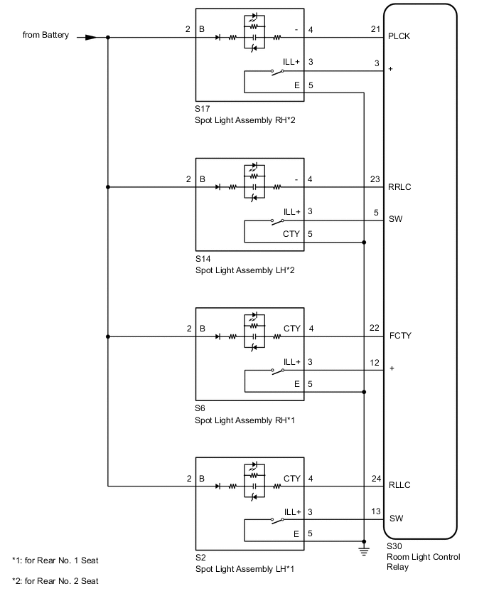
The room light control relay receives the signals of each spot light assembly switch.
WIRING DIAGRAM
CAUTION / NOTICE / HINT
Note
The lighting system uses CAN communication. First perform the inspections in "How to Proceed with Troubleshooting" to confirm that there are no communication malfunctions before proceeding with troubleshooting.
PROCEDURE
-
READ VALUE USING GTS (PERSONAL LIGHT SWITCH REAR)
-
Using the GTS, read the Data List.
OK Spot lights illuminate.
Body Electrical > ILLUMINATION > Data ListTester Display Measurement Item Range Normal Condition Diagnostic Note Personal Light Switch Rear Right 1 Spot light assembly RH (for Rear No. 1 Seat) condition ON or OFF ON: Turns spot light assembly RH (for Rear No. 1 Seat) on
OFF: Turns spot light assembly RH (for Rear No. 1 Seat) off
- Personal Light Switch Rear Right 2 Spot light assembly RH (for Rear No. 2 Seat) condition ON or OFF ON: Turns spot light assembly RH (for Rear No. 2 Seat) on
OFF: Turns spot light assembly RH (for Rear No. 2 Seat) off
- Personal Light Switch Rear Left 1 Spot light assembly LH (for Rear No. 1 Seat) condition ON or OFF ON: Turns spot light assembly LH (for Rear No. 1 Seat) on
OFF: Turns spot light assembly LH (for Rear No. 1 Seat) off
- Personal Light Switch Rear Left 2 Spot light assembly LH (for Rear No. 2 Seat) condition ON or OFF ON: Turns spot light assembly LH (for Rear No. 2 Seat) on
OFF: Turns spot light assembly LH (for Rear No. 2 Seat) off
-
Body Electrical > ILLUMINATION > Data ListTester Display Personal Light Switch Rear Right 1 Personal Light Switch Rear Right 2 Personal Light Switch Rear Left 1 Personal Light Switch Rear Left 2 OK Normal conditions listed above are displayed. Result Result Proceed to OK A NG (Spot light assembly RH [for Rear No. 1 Seat]) B NG (Spot light assembly RH [for Rear No. 2 Seat]) C NG (Spot light assembly LH [for Rear No. 1 Seat]) D NG (Spot light assembly LH [for Rear No. 2 Seat]) E
A 
PROCEED TO NEXT SUSPECTED AREA SHOWN IN PROBLEM SYMPTOMS TABLE Click here
C 
CHECK HARNESS AND CONNECTOR (SPOT LIGHT ASSEMBLY RH - ROOM LIGHT CONTROL RELAY AND BODY GROUND) Click here
D
CHECK HARNESS AND CONNECTOR (SPOT LIGHT ASSEMBLY LH - ROOM LIGHT CONTROL RELAY AND BODY GROUND) Click here
E
CHECK HARNESS AND CONNECTOR (SPOT LIGHT ASSEMBLY LH - ROOM LIGHT CONTROL RELAY AND BODY GROUND) Click here
B 
-
-
CHECK HARNESS AND CONNECTOR (SPOT LIGHT ASSEMBLY RH - ROOM LIGHT CONTROL RELAY AND BODY GROUND)
-
Disconnect the S6 spot light assembly RH connector.
-
Disconnect the S30 room light control relay connector.
-
Measure the resistance according to the value(s) in the table below.
Standard Resistance Tester Connection Condition Specified Condition S6-3 (ILL+) - S30-12 (+) Always Below 1 Ω S6-5 (E) - Body ground Always Below 1 Ω S6-3 (ILL+) or S30-12 (+) - Body ground Always 10 kΩ or higher Result Proceed to OK NG
NG
REPAIR OR REPLACE HARNESS OR CONNECTOR
OK
-
-
CHECK SPOT LIGHT ASSEMBLY RH
-
Replace the spot light assembly RH with a new or known good one.
-
Check that each function of the spot light assembly operates normally.
OK Spot lights illuminate. Result Proceed to OK NG
OK
END (SPOT LIGHT ASSEMBLY RH WAS DEFECTIVE)
NG
REPLACE ROOM LIGHT CONTROL RELAY Click here
-
-
CHECK HARNESS AND CONNECTOR (SPOT LIGHT ASSEMBLY RH - ROOM LIGHT CONTROL RELAY AND BODY GROUND)
-
Disconnect the S17 spot light assembly RH connector.
-
Disconnect the S30 room light control relay connector.
-
Measure the resistance according to the value(s) in the table below.
Standard Resistance Tester Connection Condition Specified Condition S17-3 (ILL+) - S30-3 (+) Always Below 1 Ω S17-5 (E) - Body ground Always Below 1 Ω S17-3 (ILL+) or S30-3 (+) - Body ground Always 10 kΩ or higher Result Proceed to OK NG
NG
REPAIR OR REPLACE HARNESS OR CONNECTOR
OK
-
-
CHECK SPOT LIGHT ASSEMBLY RH
-
Replace the spot light assembly RH with a new or known good one.
-
Check that each function of the spot light assembly operates normally.
OK Spot lights illuminate. Result Proceed to OK NG
OK
END (SPOT LIGHT ASSEMBLY RH WAS DEFECTIVE)
NG
REPLACE ROOM LIGHT CONTROL RELAY Click here
-
-
CHECK HARNESS AND CONNECTOR (SPOT LIGHT ASSEMBLY LH - ROOM LIGHT CONTROL RELAY AND BODY GROUND)
-
Disconnect the S2 spot light assembly LH connector.
-
Disconnect the S30 room light control relay connector.
-
Measure the resistance according to the value(s) in the table below.
Standard Resistance Tester Connection Condition Specified Condition S2-3 (ILL+) - S30-13 (SW) Always Below 1 Ω S2-5 (E) - Body ground Always Below 1 Ω S2-3 (ILL+) or S30-13 (SW) - Body ground Always 10 kΩ or higher Result Proceed to OK NG
NG
REPAIR OR REPLACE HARNESS OR CONNECTOR
OK
-
-
CHECK SPOT LIGHT ASSEMBLY LH
-
Replace the spot light assembly LH with a new or known good one.
-
Check that each function of the spot light assembly operates normally.
OK Spot lights illuminate. Result Proceed to OK NG
OK
END (SPOT LIGHT ASSEMBLY LH WAS DEFECTIVE)
NG
REPLACE ROOM LIGHT CONTROL RELAY Click here
-
-
CHECK HARNESS AND CONNECTOR (SPOT LIGHT ASSEMBLY LH - ROOM LIGHT CONTROL RELAY AND BODY GROUND)
-
Disconnect the S14 spot light assembly LH connector.
-
Disconnect the S30 room light control relay connector.
-
Measure the resistance according to the value(s) in the table below.
Standard Resistance Tester Connection Condition Specified Condition S14-3 (ILL+) - S30-5 (SW) Always Below 1 Ω S14-5 (CTY) - Body ground Always Below 1 Ω S14-3 (ILL+) or S30-5 (SW) - Body ground Always 10 kΩ or higher Result Proceed to OK NG
NG
REPAIR OR REPLACE HARNESS OR CONNECTOR
OK
-
-
CHECK SPOT LIGHT ASSEMBLY LH
-
Replace the spot light assembly LH with a new or known good one.
-
Check that each function of the spot light assembly operates normally.
OK Spot lights illuminate. Result Proceed to OK NG
OK
END (SPOT LIGHT ASSEMBLY LH WAS DEFECTIVE)
NG
REPLACE ROOM LIGHT CONTROL RELAY Click here
-