LIGHTING SYSTEM Ceiling Color Illumination Switch Circuit
DESCRIPTION
The room light control relay receives the signals of each switch from the integration control and panel assembly.
WIRING DIAGRAM
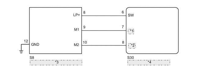
| *1 | UP |
| *2 | DOWN |
| *3 | Integration Control and Panel Assembly |
| *4 | Room Light Control Relay |
CAUTION / NOTICE / HINT
Note
The lighting system uses CAN communication. First perform the inspections in "How to Proceed with Troubleshooting" to confirm that there are no communication malfunctions before proceeding with troubleshooting.
PROCEDURE
-
READ VALUE USING GTS (REAR PERSONAL LIGHT SWITCH)
-
Using the GTS, read the Data List.
OK Spot lights illuminate.
Body Electrical > ILLUMINATION > Data ListTester Display Measurement Item Range Normal Condition Diagnostic Note Room Light Switch Integration control and panel assembly (dimmer switch) condition ON or OFF ON: Turns the integration control and panel assembly (dimmer switch) on
OFF: Turns the integration control and panel assembly (dimmer switch) off
- Color Change Switch Up Integration control and panel assembly (color select up switch) condition ON or OFF ON: Turns the integration control and panel assembly (color select up switch) on
OFF: Turns the integration control and panel assembly (color select up switch) off
- Color Change Switch Down Integration control and panel assembly (color select down switch) condition ON or OFF ON: Turns the integration control and panel assembly (color select down switch) on
OFF: Turns the integration control and panel assembly (color select down switch) off
-
Body Electrical > ILLUMINATION > Data ListTester Display Room Light Switch Color Change Switch Up Color Change Switch Down OK The display is as specified in the normal condition column. Result Proceed to OK NG
OK 
PROCEED TO NEXT SUSPECTED AREA SHOWN IN PROBLEM SYMPTOMS TABLE Click here
NG 
-
-
INSPECT INTEGRATION CONTROL AND PANEL ASSEMBLY
-
Remove the integration control and panel assembly.
-
Inspect the integration control and panel assembly.
Result Proceed to OK NG
NG
REPLACE INTEGRATION CONTROL AND PANEL ASSEMBLY Click here
OK
-
-
CHECK HARNESS AND CONNECTOR (INTEGRATION CONTROL AND PANEL ASSEMBLY - ROOM LIGHT CONTROL RELAY AND BODY GROUND)
-
Disconnect the S30 room light control relay connector.
-
Disconnect the S8 integration control and panel assembly connector.
-
Measure the resistance according to the value(s) in the table below.
Standard Resistance Tester Connection Condition Specified Condition S30-6 (SW) - S8-8 (LP+) Always Below 1 Ω S30-7 (UP) - S8-9 (M1) Always Below 1 Ω S30-8 (DOWN) - S8-10 (M2) Always Below 1 Ω S8-12 (GND) - Body ground Always Below 1 Ω S30-6 (SW) or S8-8 (LP+) - Body ground Always 10 kΩ or higher S30-7 (UP) or S8-9 (M1) - Body ground Always 10 kΩ or higher S30-8 (DOWN) or S8-10 (M2) - Body ground Always 10 kΩ or higher Result Proceed to OK NG
OK
REPLACE ROOM LIGHT CONTROL RELAY Click here
NG
REPAIR OR REPLACE HARNESS OR CONNECTOR
-