LIGHTING SYSTEM Ceiling Color Illumination Circuit
DESCRIPTION
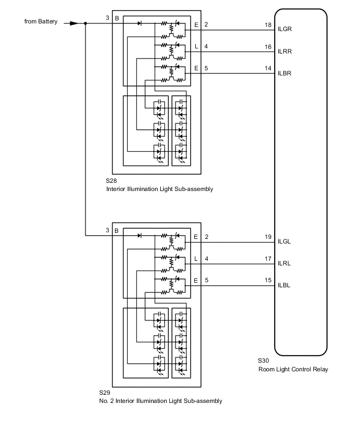
The room light control relay controls the illumination of the interior illumination lights (roof color illumination) and spot light assemblies.
WIRING DIAGRAM
CAUTION / NOTICE / HINT
Note
The lighting system uses CAN communication. First perform the inspections in "How to Proceed with Troubleshooting" to confirm that there are no communication malfunctions before proceeding with troubleshooting.
PROCEDURE
-
PERFORM ACTIVE TEST USING GTS (COLOR LED)
-
Using the GTS, perform the Active Test.
Body Electrical > ILLUMINATION > Active TestTester Display Measurement Item Control Range Diagnostic Note Color LED (Yellow) Illuminates the LEDs of the interior illumination light (roof color illumination) and No. 2 interior illumination light (roof color illumination) (yellow) ON or OFF - Color LED (Green) Illuminates the LEDs of the interior illumination light (roof color illumination) and No. 2 interior illumination light (roof color illumination) (green) ON or OFF - Color LED (Blue) Illuminates the LEDs of the interior illumination light (roof color illumination) and No. 2 interior illumination light (roof color illumination) (blue) ON or OFF -
Body Electrical > ILLUMINATION > Active TestTester Display Color LED (Yellow)
Body Electrical > ILLUMINATION > Active TestTester Display Color LED (Green)
Body Electrical > ILLUMINATION > Active TestTester Display Color LED (Blue) OK The Active Test is performed normally. Result Result Proceed to OK A None of the LEDs on one side iluminate B Any one of the LEDs on one side does not iluminate C
A 
PROCEED TO NEXT SUSPECTED AREA SHOWN IN PROBLEM SYMPTOMS TABLE Click here
C 
CHECK HARNESS AND CONNECTOR (INTERIOR ILLUMINATION LIGHT SUB-ASSEMBLY - ROOM LIGHT CONTROL RELAY) Click here
B 
-
-
CHECK INTERIOR ILLUMINATION LIGHT SUB-ASSEMBLY POWER SOURCE CIRCUIT
-

*a Front view of wire harness connector
(to Interior Illumination Light Sub-assembly)
for RH Side:
-
Disconnect the interior illumination light sub-assembly connector.
-
Measure the voltage according to the value(s) in the table below.
Standard Voltage Tester Connection Condition Specified Condition S28-3 (B) - Body ground Battery saving control (interior light auto cut function) not operating 11 to 14 V
-
-
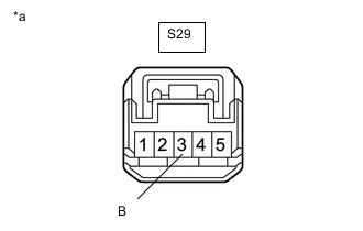
*a Front view of wire harness connector
(to Interior Illumination Light Sub-assembly)
for LH Side:
-
Disconnect the interior illumination light sub-assembly connector.
-
Measure the voltage according to the value(s) in the table below.
Standard Voltage Tester Connection Condition Specified Condition S29-3 (B) - Body ground Battery saving control (interior light auto cut function) not operating 11 to 14 V
Result Proceed to OK (for RH Side) OK (for LH Side) NG -
OK (for RH Side)
REPLACE INTERIOR ILLUMINATION LIGHT SUB-ASSEMBLY Click here
OK (for LH Side)
REPLACE NO. 2 INTERIOR ILLUMINATION LIGHT SUB-ASSEMBLY Click here
NG
REPAIR OR REPLACE HARNESS OR CONNECTOR
-
-
CHECK HARNESS AND CONNECTOR (INTERIOR ILLUMINATION LIGHT SUB-ASSEMBLY - ROOM LIGHT CONTROL RELAY)
-
for RH Side:
-
Disconnect the S30 room light control relay connector.
-
Disconnect the S28 interior illumination light sub-assembly connector.
-
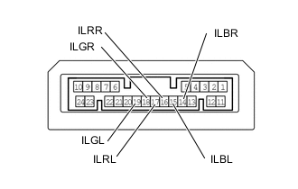
Measure the resistance according to the value(s) in the table below.
Standard Resistance Tester Connection Condition Specified Condition S30-18 (ILGR) - S28-2 (E) Always Below 1 Ω S30-16 (ILRR) - S28-4 (L) Always Below 1 Ω S30-14 (ILBR) - S28-5 (E) Always Below 1 Ω S30-18 (ILGR) or S28-2 (E) - Body ground Always 10 kΩ or higher S30-16 (ILRR) or S28-4 (L) - Body ground Always 10 kΩ or higher S30-14 (ILBR) or S28-5 (E) - Body ground Always 10 kΩ or higher
-
-
for LH Side:
-
Disconnect the S30 room light control relay connector.
-
Disconnect the S29 interior illumination light sub-assembly connector.
-
Measure the resistance according to the value(s) in the table below.
Standard Resistance Tester Connection Condition Specified Condition S30-19 (ILGL) - S29-2 (E) Always Below 1 Ω S30-17 (ILRL) - S29-4 (L) Always Below 1 Ω S30-15 (ILBL) - S29-5 (E) Always Below 1 Ω S30-19 (ILGL) or S29-2 (E) - Body ground Always 10 kΩ or higher S30-17 (ILRL) or S29-4 (L) - Body ground Always 10 kΩ or higher S30-15 (ILBL) or S29-5 (E) - Body ground Always 10 kΩ or higher
Result Proceed to OK NG -
NG
REPAIR OR REPLACE HARNESS OR CONNECTOR
OK
-
-
INSPECT ROOM LIGHT CONTROL RELAY
-
Remove the room light control relay.
-
Measure the resistance according to the value(s) in the table below.
Standard Resistance Tester Connection Condition Specified Condition 18 (ILGR) - 19 (ILGL) Always Below 1 Ω 16 (ILRR) - 17 (ILRL) Always Below 1 Ω 14 (ILBR) - 15 (ILBL) Always Below 1 Ω Result Proceed to OK (for RH Side) OK (for LH Side) NG
OK (for RH Side)
REPLACE INTERIOR ILLUMINATION LIGHT SUB-ASSEMBLY Click here
OK (for LH Side)
REPLACE NO. 2 INTERIOR ILLUMINATION LIGHT SUB-ASSEMBLY Click here
NG
REPLACE ROOM LIGHT CONTROL RELAY Click here
-