LIGHTING SYSTEM TERMINALS OF ECU
-
CHECK JUNCTION BLOCK ASSEMBLY LH, MAIN BODY ECU (MULTIPLEX NETWORK BODY ECU)

*A Main Body ECU (Multiplex Network Body ECU) with 2 Connectors - - *1 Main Body ECU (Multiplex Network Body ECU) - - 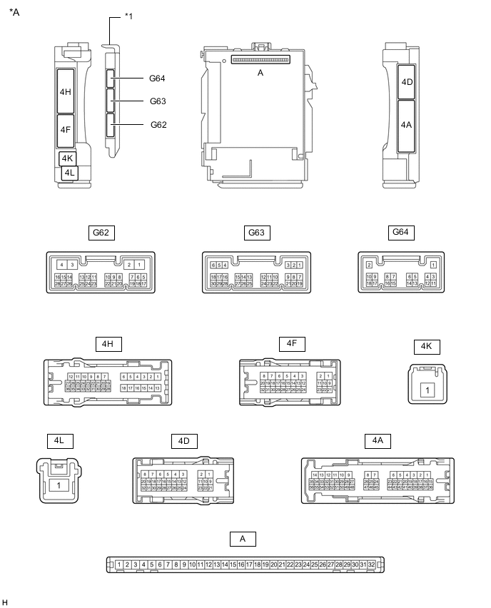
*A Main Body ECU (Multiplex Network Body ECU) with 3 Connectors - - *1 Main Body ECU (Multiplex Network Body ECU) - -
-
Remove the main body ECU (multiplex network body ECU) from the junction block assembly LH.
-
Connect the junction block assembly LH connectors.
-
Measure the voltage and resistance according to the value(s) in the table below.
Terminal No. (Symbol) Wiring Color Terminal Description Condition Specified Condition A-32 (IG) - Body ground - Ignition power supply Engine switch on (IG) 11 to 14 V Engine switch off Below 1 V A-31 (BECU) - Body ground - Battery power supply Always 11 to 14 V A-30 (ACC) - Body ground - ACC power supply Engine switch on (ACC) 11 to 14 V Engine switch off Below 1 V A-11 (GND1) - Body ground - Ground Always Below 1 Ω If the result is not as specified, there may be a malfunction in the wire harness or junction block assembly LH.
-
Install the main body ECU (multiplex network body ECU).
-
Measure the voltage, resistance and pulse according to the value(s) in the table below.
Terminal No. (Symbol) Wiring Color Terminal Description Condition Specified Condition G63-6 (FLCY) - Body ground GR - Body ground Front door courtesy light switch LH signal Front door LH open Below 1 V Front door LH closed Pulse generation G63-27 (FRCY) - Body ground L - Body ground Front door courtesy light switch RH signal Front door RH open Below 1 V Front door RH closed Pulse generation G62-2 (LSWR) - Body ground V - Body ground Slide door unlock detection switch RH signal Slide door RH unlocked Below 1 V Engine switch off, all doors closed and slide door RH locked Pulse generation 4A-38 (LSFR) - Body ground Y - Body ground Front door unlock detection switch RH signal Front door RH unlocked Below 1 V Engine switch off, all doors closed and front door RH locked Pulse generation 4D-18 (RCTY) - Body ground LG - Body ground Slide door courtesy light switch RH signal Slide door RH open Below 1 V Slide door RH closed Pulse generation 4H-35 (LSWL) - Body ground SB - Body ground Slide door unlock detection switch LH signal Slide door LH unlocked Below 1 V Engine switch off, all doors closed and slide door LH locked Pulse generation 4H-23 (LCTY) - Body ground L - Body ground Slide door courtesy light switch LH signal Slide door LH open Below 1 V Slide door LH closed Pulse generation 4H-22 (LSFL) - Body ground SB - Body ground Front door unlock detection switch LH signal Front door LH unlocked Below 1 V Engine switch off, all doors closed and front door LH locked Pulse generation 4H-36 (LGCY) - Body ground L - Body ground Back door courtesy light switch signal Back door open Below 1 V Back door closed Pulse generation 4A-27 (DOMR) - Body ground R - Body ground Battery saving control (interior light auto cut function) signal Battery saving control (interior light auto cut function) operating Below 1 V Battery saving control (interior light auto cut function) not operating 11 to 14 V 4D-14 (ILE) - Body ground W - Body ground Map light and spot light signal Battery saving control (interior light auto cut function) not operating, map light and spot light on using illuminated entry system Below 1 V Battery saving control (interior light auto cut function) not operating, map light and spot light off using illuminated entry system 11 to 14 V 4D-25 (FSPT) - Body ground SB - Body ground Interior illumination light LH signal Interior illumination LH light on Below 1 V Interior illumination LH light off 11 to 14 V 4D-26 (FSPT) - Body ground R - Body ground Interior illumination light RH signal Interior illumination RH light on Below 1 V Interior illumination RH light off 11 to 14 V G62-1 (FLCL) - Body ground*1 LA-B - Body ground Courtesy light assembly LH signal Battery saving control (interior light auto cut function) not operating, map light and spot light on using illuminated entry system Below 1 V Battery saving control (interior light auto cut function) not operating, map light and spot light off using illuminated entry system 11 to 14 V G62-17 (FRCL) - Body ground*1 W - Body ground Courtesy light assembly RH signal Battery saving control (interior light auto cut function) not operating, map light and spot light on using illuminated entry system Below 1 V Battery saving control (interior light auto cut function) not operating, map light and spot light off using illuminated entry system 11 to 14 V G62-27 (DMDR) - Body ground*2 R - Body ground Ground Always Below 1 Ω G62-27 (DMDR) - Body ground*3 R - Body ground Map light assembly (Door switch) signal input Map light assembly (Door switch) off 11 to 14 V Map light assembly (Door switch) on Below 1 V G62-28 (DMON) - Body ground*3 P - Body ground Map light assembly (Dome switch) signal input Map light assembly (Dome switch) on Below 1 V Map light assembly (Dome switch) off Pulse generation *1: w/ Courtesy Light
*2: for Bulb Type
*3: for LED Type
-
-
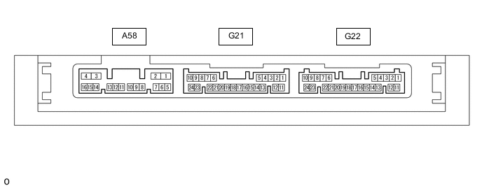
CHECK CERTIFICATION ECU (SMART KEY ECU ASSEMBLY)
-
Disconnect the G22 certification ECU connector.
-
Measure the voltage and resistance according to the value(s) in the table below.
Terminal No. (Symbol) Wiring Color Terminal Description Condition Specified Condition G22-10 (+B) - Body ground GR - Body ground Battery power supply Always 11 to 14 V G22-11 (E) - Body ground W-B - Body ground Ground Always Below 1 Ω If the result is not as specified, there may be a malfunction on the wire harness side.
-
Reconnect the G22 certification ECU connector.
-
Measure the voltage according to the value(s) in the table below.
Terminal No. (Symbol) Wiring Color Terminal Description Condition Specified Condition G22-17 (SWIL) - G22-12 (AGND) P - W Engine switch illumination operation signal Engine switch illumination on 11 to 14 V Engine switch illumination off Below 1 V
-
-
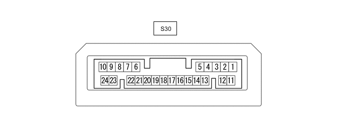
CHECK ROOM LIGHT CONTROL RELAY
-
Measure the voltage, pulse and resistance according to the value(s) in the table below.
Terminal No. (Symbol) Wiring Color Terminal Description Condition Specified Condition S30-2 (E) - Body ground W-B - Body ground Ground Always Below 1 Ω S30-3 (+) - Body ground*1, *3 W - Body ground Spot light assembly RH signal Spot light assembly RH on Below 1 Ω Spot light assembly RH off 10 kΩ or higher S30-4 (ECUB1) - Body ground SB - Body ground Battery power supply Always 11 to 14 V S30-5 (SW) - Body ground*1, *3 P - Body ground Spot light assembly LH signal Spot light assembly LH on Below 1 Ω Spot light assembly LH off 10 kΩ or higher S30-6 (SW) - Body ground P - Body ground Integration control and panel assembly (dimmer switch) signal Integration control and panel assembly (dimmer switch) on Below 1 Ω Integration control and panel assembly (dimmer switch) off 10 kΩ or higher S30-7 (UP) - Body ground B - Body ground Integration control and panel assembly (color select up switch) signal Integration control and panel assembly (color select up switch) on Below 1 Ω Integration control and panel assembly (color select up switch) off 10 kΩ or higher S30-8 (DOWN) - Body ground W - Body ground Integration control and panel assembly (color select down switch) signal Integration control and panel assembly (color select down switch) on Below 1 Ω Integration control and panel assembly (color select down switch) off 10 kΩ or higher S30-12 (+) - Body ground*1, *2 B - Body ground Spot light assembly RH signal Spot light assembly RH on Below 1 Ω Spot light assembly RH off 10 kΩ or higher S30-13 (SW) - Body ground*1, *2 V - Body ground Spot light assembly LH signal Spot light assembly LH on Below 1 Ω Spot light assembly LH off 10 kΩ or higher S30-21 (PLCK) - Body ground*1, *3 R - Body ground Spot light assembly RH signal Spot light assembly RH on Below 1 V Spot light assembly RH off 11 to 14 V Spot light assembly RH off→Spot light assembly RH operated 2 or 3 times Pulse generation S30-22 (FCTY) - Body ground*1, *2 GR - Body ground Spot light assembly RH signal Spot light assembly RH on Below 1 V Spot light assembly RH off 11 to 14 V Spot light assembly RH off→Spot light assembly RH operated 2 or 3 times Pulse generation S30-23 (RRLC) - Body ground*1, *3 SB - Body ground Spot light assembly LH signal Spot light assembly LH on Below 1 V Spot light assembly LH off 11 to 14 V Spot light assembly LH off→Spot light assembly LH operated 2 or 3 times Pulse generation S30-24 (RLLC) - Body ground*1, *2 L - Body ground Spot light assembly LH signal Spot light assembly LH on Below 1 V Spot light assembly LH off 11 to 14 V Spot light assembly LH off→Spot light assembly LH operated 2 or 3 times Pulse generation *1: for LED Type
*2: for Rear No. 1 Seat
*3: for Rear No. 2 Seat
-
Measure the voltage and pulse according to the value(s) in the table below using active test.
Terminal No. (Symbol) Wiring Color Terminal Description Condition Specified Condition S30-14 (ILBR) - Body ground L - Body ground Interior illumination light sub-assembly signal Active Test "Color LED (Blue)" is "ON" 11 to 14 V Active Test "Color LED (Blue)" is "OFF" Below 1 V Active Test "Color LED (Blue) Modulated Light" is "ON" Pulse generation S30-15 (ILBL) - Body ground L - Body ground Interior illumination light sub-assembly signal Active Test "Color LED (Blue)" is "ON" 11 to 14 V Active Test "Color LED (Blue)" is "OFF" Below 1 V Active Test "Color LED (Blue) Modulated Light" is "ON" Pulse generation S30-16 (ILRR) - Body ground R - Body ground Interior illumination light sub-assembly signal Active Test "Color LED (Yellow)" is "ON" 11 to 14 V Active Test "Color LED (Yellow)" is "OFF" Below 1 V Active Test "Color LED (Yellow) Modulated Light" is "ON" Pulse generation S30-17 (ILRL) - Body ground R - Body ground Interior illumination light sub-assembly signal Active Test "Color LED (Yellow)" is "ON" 11 to 14 V Active Test "Color LED (Yellow)" is "OFF" Below 1 V Active Test "Color LED (Yellow) Modulated Light" is "ON" Pulse generation S30-18 (ILGR) - Body ground G - Body ground Interior illumination light sub-assembly signal Active Test "Color LED (Green)" is "ON" 11 to 14 V Active Test "Color LED (Green)" is "OFF" Below 1 V Active Test "Color LED (Green) Modulated Light" is "ON" Pulse generation S30-19 (ILGL) - Body ground G - Body ground Interior illumination light sub-assembly signal Active Test "Color LED (Green)" is "ON" 11 to 14 V Active Test "Color LED (Green)" is "OFF" Below 1 V Active Test "Color LED (Green) Modulated Light" is "ON" Pulse generation
-
-
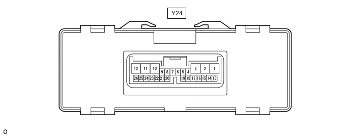
REAR SEAT CLIMATE CONTROL ECU LH (w/ Reading Light)
-
Disconnect the Y24 rear seat climate control ECU LH connector.
-
Measure the voltage and resistance according to the value(s) in the table below.
Terminal No. (Symbol) Wiring Color Terminal Description Condition Specified Condition Y24-13 (+B) - Body ground P - Body ground Battery power supply Always 11 to 14 V Y24-12 (IG) - Body ground B - Body ground Ignition power supply Engine switch off Below 1 V Engine switch on (IG) 11 to 14 V Y24-3 (GND) - Body ground W - Body ground Ground Always Below 1 Ω -
Reconnect the Y24 rear seat climate control ECU LH connector.
-
Measure the voltage and pulse according to the value(s) in the table below.
Terminal No. (Symbol) Wiring Color Terminal Description Condition Specified Condition Y24-9 (RSWM) - Body ground GR - Body ground Rear power seat switch LH (main switch) signal Rear power seat switch LH (main switch) on Below 1 V Rear power seat switch LH (main switch) off 11 to 14 V Y24-22 (RSWU) - Body ground R - Body ground Rear power seat switch LH (up switch) signal Rear power seat switch LH (up switch) on Below 1 V Rear power seat switch LH (up switch) off 11 to 14 V Y24-23 (RSWD) - Body ground BE - Body ground Rear power seat switch LH (down switch) signal Rear power seat switch LH (down switch) on Below 1 V Rear power seat switch LH (down switch) off 11 to 14 V Y24-25 (RDLP) - Body ground P - Body ground No. 2 spot light assembly LH signal No. 2 spot light assembly LH on 11 to 14 V No. 2 spot light assembly LH off Below 1 V No. 2 spot light assembly LH on and rear power seat switch LH (up or dome switch) on Pulse generation
-
-
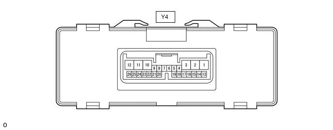
REAR SEAT CLIMATE CONTROL ECU RH (w/ Reading Light)
-
Disconnect the Y4 rear seat climate control ECU RH connector.
-
Measure the voltage and resistance according to the value(s) in the table below.
Terminal No. (Symbol) Wiring Color Terminal Description Condition Specified Condition Y4-13 (+B) - Body ground P - Body ground Battery power supply Always 11 to 14 V Y4-12 (IG) - Body ground B - Body ground Ignition power supply Engine switch off Below 1 V Engine switch on (IG) 11 to 14 V Y4-3 (GND) - Body ground W - Body ground Ground Always Below 1 Ω -
Reconnect the Y4 rear seat climate control ECU RH connector.
-
Measure the voltage and pulse according to the value(s) in the table below.
Terminal No. (Symbol) Wiring Color Terminal Description Condition Specified Condition Y4-9 (RSWM) - Body ground GR - Body ground Rear power seat switch RH (main switch) signal Rear power seat switch RH (main switch) on Below 1 V Rear power seat switch RH (main switch) off 11 to 14 V Y4-22 (RSWU) - Body ground R - Body ground Rear power seat switch RH (up switch) signal Rear power seat switch RH (up switch) on Below 1 V Rear power seat switch RH (up switch) off 11 to 14 V Y4-23 (RSWD) - Body ground BE - Body ground Rear power seat switch RH (down switch) signal Rear power seat switch RH (down switch) on Below 1 V Rear power seat switch RH (down switch) off 11 to 14 V Y4-25 (RDLP) - Body ground P - Body ground No. 2 spot light assembly RH signal No. 2 spot light assembly RH on 11 to 14 V No. 2 spot light assembly RH off Below 1 V No. 2 spot light assembly RH on and rear power seat switch RH (up or down switch) on Pulse generation
-