LIGHTING SYSTEM Interior Light Circuit
DESCRIPTION
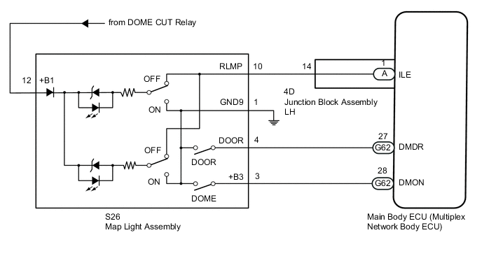
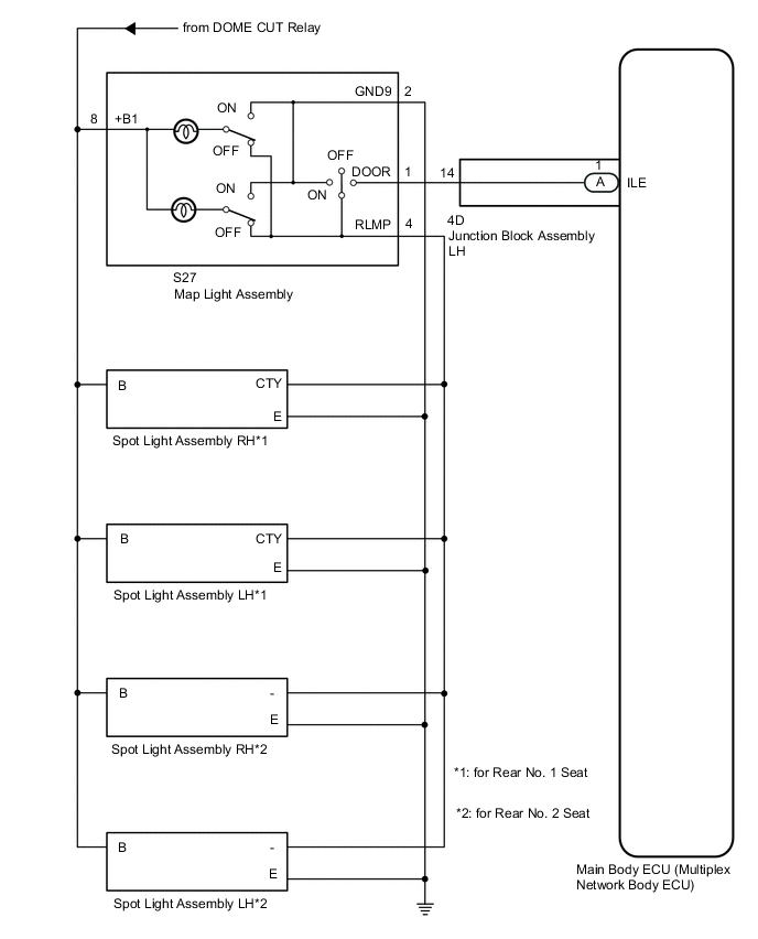
The main body ECU (multiplex network body ECU) controls the map light assembly and spot light assembly.
WIRING DIAGRAM
for LED Type:
for Bulb Type:
CAUTION / NOTICE / HINT
Note
-
If the main body ECU (multiplex network body ECU) is replaced, refer to the Service Bulletin.
-
As the door control battery is installed between the vehicle battery and main body ECU (multiplex network body ECU), first perform the inspections in On-vehicle Inspection to confirm that there are no malfunctions in the power source circuit for the main body ECU (multiplex network body ECU) before performing this troubleshooting procedure.
-
Inspect the fuses and bulb for circuits related to this system before performing the following procedure.
PROCEDURE
-
PERFORM ACTIVE TEST USING GTS (ILLUMINATED ENTRY SYSTEM)
-
Using the GTS, perform the Active Test.
Body Electrical > Main Body > Active TestTester Display Measurement Item Control Range Diagnostic Note Illuminated Entry System Turns on the lights that are controlled by the illuminated entry system* ON or OFF Perform the Active Test with the door switch in the map light assembly turned on.
-
*: Refer to Description for the lights that are controlled by the illuminated entry system.
Body Electrical > Main Body > Active TestTester Display Illuminated Entry System OK Map light and spot light come on. Result Proceed to OK NG (for LED Type) NG (for Bulb Type) -
OK 
PROCEED TO NEXT SUSPECTED AREA SHOWN IN PROBLEM SYMPTOMS TABLE Click here
NG (for Bulb Type) 
INSPECT MAP LIGHT ASSEMBLY Click here
NG (for LED Type) 
-
-
INSPECT MAP LIGHT ASSEMBLY
-
Remove the map light assembly.
-
Inspect the map light assembly.
Result Proceed to OK NG
NG
REPLACE MAP LIGHT ASSEMBLY Click here
OK
-
-
CHECK HARNESS AND CONNECTOR (MAP LIGHT ASSEMBLY - BATTERY AND BODY GROUND)
-
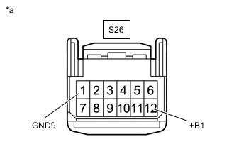
*a Front view of wire harness connector
(to Map Light Assembly)
Disconnect the S26 map light assembly connector.
-
Measure the voltage according to the value(s) in the table below.
Standard Voltage Tester Connection Condition Specified Condition S26-12 (+B1) - Body ground Battery saving control (interior light auto cut function) not operating 11 to 14 V -
Measure the resistance according to the value(s) in the table below.
Standard Resistance Tester Connection Condition Specified Condition S26-1 (GND9) - Body ground Always Below 1 Ω Result Proceed to OK NG
NG
REPAIR OR REPLACE HARNESS OR CONNECTOR
OK
-
-
CHECK HARNESS AND CONNECTOR (MAP LIGHT ASSEMBLY - MAIN BODY ECU [MULTIPLEX NETWORK BODY ECU])
-
Disconnect the S26 map light assembly connector.
-
Remove the junction block assembly LH.
-
Remove the main body ECU (multiplex network body ECU) from the junction block assembly LH.
-
Connect the 4D junction block assembly LH connector.
-
Measure the resistance according to the value(s) in the table below.
Standard Resistance Tester Connection Condition Specified Condition S26-10 (RLMP) - A-1 (ILE) Always Below 1 Ω S26-10 (RLMP) or A-1 (ILE) - Body ground Always 10 kΩ or higher Result Proceed to OK NG
OK
REPLACE MAIN BODY ECU (MULTIPLEX NETWORK BODY ECU) Click here
NG
-
-
CHECK HARNESS AND CONNECTOR (MAP LIGHT ASSEMBLY - MAIN BODY ECU [MULTIPLEX NETWORK BODY ECU])
-
Disconnect the S26 map light assembly connector.
-
Disconnect the 4D junction block assembly LH connector.
-
Measure the resistance according to the value(s) in the table below.
Standard Resistance Tester Connection Condition Specified Condition S26-10 (RLMP) - 4D-14 Always Below 1 Ω S26-10 (RLMP) or 4D-14 - Body ground Always 10 kΩ or higher Result Proceed to OK NG
OK
REPLACE JUNCTION BLOCK ASSEMBLY LH Click here
NG
REPAIR OR REPLACE HARNESS OR CONNECTOR
-
-
INSPECT MAP LIGHT ASSEMBLY
-
Remove the map light assembly.
-
Inspect the map light assembly.
Result Proceed to OK NG
NG
REPLACE MAP LIGHT ASSEMBLY Click here
OK
-
-
CHECK HARNESS AND CONNECTOR (MAP LIGHT ASSEMBLY - BATTERY AND BODY GROUND)
-
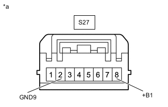
*a Front view of wire harness connector
(to Map Light Assembly)
Disconnect the S27 map light assembly connector.
-
Measure the voltage according to the value(s) in the table below.
Standard Voltage Tester Connection Condition Specified Condition S27-8 (+B1) - Body ground Battery saving control (interior light auto cut function) not operating 11 to 14 V -
Measure the resistance according to the value(s) in the table below.
Standard Resistance Tester Connection Condition Specified Condition S27-2 (GND9) - Body ground Always Below 1 Ω Result Proceed to OK NG
NG
REPAIR OR REPLACE HARNESS OR CONNECTOR
OK
-
-
CHECK HARNESS AND CONNECTOR (MAP LIGHT ASSEMBLY - MAIN BODY ECU [MULTIPLEX NETWORK BODY ECU])
-
Disconnect the S27 map light assembly connector.
-
Remove the junction block assembly LH.
-
Remove the main body ECU (multiplex network body ECU) from the junction block assembly LH.
-
Connect the 4D junction block assembly LH connector.
-
Measure the resistance according to the value(s) in the table below.
Standard Resistance Tester Connection Condition Specified Condition S27-1 (DOOR) - A-1 (ILE) Always Below 1 Ω S27-1 (DOOR) or A-1 (ILE) - Body ground Always 10 kΩ or higher Result Proceed to OK NG
NG
CHECK HARNESS AND CONNECTOR (MAP LIGHT ASSEMBLY - MAIN BODY ECU [MULTIPLEX NETWORK BODY ECU]) Click here
OK
-
-
CHECK HARNESS AND CONNECTOR (MAP LIGHT ASSEMBLY - SPOT LIGHT ASSEMBLY)
-
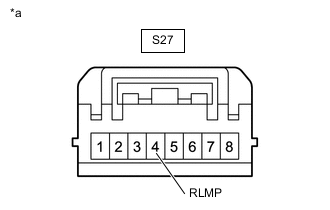
*a Front view of wire harness connector
(to Map Light Assembly)
Disconnect the S27 map light assembly connector.
-
Measure the voltage according to the value(s) in the table below.
Standard Voltage Tester Connection Condition Specified Condition S27-4 (RLMP) - Body ground Battery saving control (interior light auto cut function) not operating and any spot light assembly switch off 11 to 14 V Result Proceed to OK NG
OK
REPLACE MAIN BODY ECU (MULTIPLEX NETWORK BODY ECU) Click here
NG
REPAIR OR REPLACE HARNESS OR CONNECTOR
-
-
CHECK HARNESS AND CONNECTOR (MAP LIGHT ASSEMBLY - MAIN BODY ECU [MULTIPLEX NETWORK BODY ECU])
-
Disconnect the S27 map light assembly connector.
-
Disconnect the 4D junction block assembly LH connector.
-
Measure the resistance according to the value(s) in the table below.
Standard Resistance Tester Connection Condition Specified Condition S27-1 (DOOR) - 4D-14 Always Below 1 Ω S27-1 (DOOR) or 4D-14 - Body ground Always 10 kΩ or higher Result Proceed to OK NG
OK
REPLACE JUNCTION BLOCK ASSEMBLY LH Click here
NG
REPAIR OR REPLACE HARNESS OR CONNECTOR
-